")
")
| Issue |
Int. J. Simul. Multisci. Des. Optim.
Volume 5, 2014
|
|
|---|---|---|
| Article Number | A13 | |
| Number of page(s) | 14 | |
| DOI | https://doi.org/10.1051/smdo/2013005 | |
| Published online | 2014年2月10日 | |
Article
Mathematical methodology for optimization of the clamping forces accounting for workpiece vibratory behaviour
Mechanics Modelling and Production Research Unit (U2MP), University of Sfax, National Engineering School of Sfax (E.N.I.S.), B.P. 3038
Sfax, Tunisia
* e-mail: 该Email地址已收到反垃圾邮件插件保护。要显示它您需要在浏览器中启用JavaScript。
Received:
15
October
2013
Accepted:
13
November
2013
Abstract
This paper addresses the problem of determining the minimum clamping forces that ensure the dynamic fixturing stability. The clamping force optimization problem is formulated as a bi-level nonlinear programming problem and solved using a computational intelligence technique called particle swarm optimization (PSO). Indeed, we present an innovative simulation methodology that is able to study the effects of fixture-workpiece system dynamics and the continuously change due to material removal on fixturing stability and the minimum required clamping forces during machining. The dynamic behaviour of the fixtured workpiece subjected to time-and space-varying machining loads is simulated using a forced vibration model based on the regenerative vibrations of the cutter and workpiece excited by the dynamic cutting forces. Indeed, Material removal significantly affects the fixture-workpiece system dynamics and subsequently the minimum clamping forces required for achieving fixturing dynamic stability.
Key words: Machining / Fixturing / Stability / Vibration / Clamping / Optimization
© R. Chaari et al., Published by EDP Sciences, 2014
 This is an Open Access article distributed under the terms of the Creative Commons Attribution License (http://creativecommons.org/licenses/by/4.0), which permits unrestricted use, distribution, and reproduction in any medium, provided the original work is properly cited.
1 Introduction
In reality, machining processes such as milling are characterized by periodic forces. When the cutting frequency is near one of the natural frequencies of the fixture-workpiece system, consideration of dynamic effects in fixturing analysis is crucial. Therefore, the workpiece must remain stable in the fixture during machining in order to achieve operational safety and desired machining accuracy. In general, fixturing stability refers to the ability of the fixture to fully restrain the workpiece during the entire cutting process. As such, loss of contact and gross sliding during machining are considered to be indicators of an unstable workpiece and an inappropriate fixture design. These instabilities should be eliminated through correct design of the fixture and appropriate clamped forces.
This paper presents a dynamic model that study the effects of fixture-workpiece system dynamics and the continuously change due to material removal on fixturing stability and the minimum required clamping forces during machining. However, the majority of prior work treats the fixture-workpiece system as quasi-static and ignores the system dynamics. For example, De Meter et al. [1] considered the system deformation to be static for both clamping and machining and developed a linear programming (LP) model to compute the minimum required clamp pre-loads to prevent workpiece slip at the fixture-workpiece contacts during machining. Kang et al. [2] found the minimum clamping forces with the help of a contact stability index sensitivity matrix that is essentially a variation of the friction cone concept. Meyer and Liou [3] also developed an LP model in which the machining loads were varying and discretized over time but the system dynamics was ignored. Goals other than fixturing stability can be achieved through clamping force optimization. Hurtado and Melkote [4] formulated a multi-objective optimization model that found the minimum clamping loads to achieve workpiece shape conformability and fixture stiffness goals for a workpiece subjected to quasi-static machining forces. Chen et al. [5] presented a deformation control approach based on fixture layout design and clamping force optimization. In his approach, workpiece deformation measured accounting for chip removal effect, but the model contact is modelled by a linear spring based on Hertz contact theory. Zheng et al. [6, 7] presented a study of fixture stiffness. In first time Zheng et al. [6] developed a systematic FEA model to predict the fixture unit stiffness. In his model the contact problem is based on the penalty function method. In second time Zheng et al. [7] extended their study by an experimental study to identify the contact stiffness parameter. The normal and tangential contact stiffness is estimated by static and dynamic methods.
Gui et al. [8] and Li and Melkote [9] examined the impact of clamping forces on workpiece location accuracy. Vishnupriyan et al. [10] proposed a genetic algorithm (GA) for optimizing the machining fixture layout for minimum machining error satisfying the tolerance requirements. A number of researchers (e.g., Wang et al. [11], Tao et al. [12], Liu and Strong [13]) proposed the idea of dynamic clamping because the minimum clamping loads required to stabilize a workpiece are dependent on the position of the cutting tool. They selected sampled tool-path points where the peak machining force was assumed to act and the clamping forces were adjusted using static linear or nonlinear optimization models.
Ignoring the material removal effect and thus the continuous change of system geometry and inertia can, as shown later in this paper, lead to erroneous the prediction of the required clamping forces for fixturing stability especially when a large percentage of material is removed. Several researchers considered system dynamics in their work. Mittal et al. [14] modelled a fixture-workpiece system using the dynamic analysis and design system (DADS) software and modelled the fixture-workpiece contact as a lumped spring-damper-actuator element. Liao and Hu [15] extended Mittal et al.’s work by including the workpiece compliance effect and contact friction through combined use of the finite element (FE) method and DADS. In both studies, separation between the fixture elements and the workpiece during machining was checked for a given set of clamping forces, but macro-slip was not considered. Li and Melkote [16] modelled the change of the workpiece gravity during machining. Kaya and Ozturk [17] applied an FE-based element death technique to simulate the chip removal process for fixture layout verification. However, both papers treat the fixture-workpiece system as quasi-static. On the other hand, Deng and Melkote [18] developed a model capable to determine the minimum required clamping forces for dynamically stable fixturing. This developed model takes account to the material removal effect and the fixture-workpiece system dynamics on the fixturing stability. But they didn’t take account to the regenerative vibrations effect.
This paper addresses the problem of determining the minimum required clamping forces that ensure the fixture-workpiece dynamic stability during machining. The determination of the minimum required clamping forces takes account to the material removal effect and the fixture-workpiece system dynamics on the fixturing stability. The dynamic behaviour of the fixtured workpiece subjected to time-and space-varying machining loads is simulated using a forced vibration model based on the regenerative vibrations of the cutter and workpiece excited by the dynamic cutting forces. The clamping force optimization problem is formulated as a bi-level nonlinear programming problem and solved using a computational intelligence technique called particle swarm optimization (PSO). Through a simulation example, insight into the effects of fixture-workpiece system dynamics and its continuous change due to material removal on fixturing stability and the minimum required clamping forces is obtained.
2 Problem formulation and approach
This study focuses on machining workpieces surrounded by L locators and C clamps as shown schematically in Figure 1.
Three coordinate systems are used to describe the position and orientation of the workpiece (see Figure 1): global coordinate system (XYZ), workpiece coordinate system (xyz), which is fixed to the mass center of the workpiece with its coordinate axes coinciding with the principal inertia axes of the initial workpiece shape, and local coordinate system (xiyizi), which is fixed at each fixture-workpiece contact. Matrices are represented in the workpiece coordinate system (xyz) unless noted otherwise. The workpiece undergoes dynamic and static motion during clamping and machining, slip, and/or lift-off at the contact regions. From the standpoint of operational safety and machining accuracy, lift-off and macro-slip at the fixture-workpiece contacts during machining are undesirable because they result in loss of total restraint of the workpiece in the fixture. To eliminate these two types of fixturing instabilities, the dynamic stability of the fixtured workpiece during machining must be properly assured. An important design variable is the clamping forces applied to the workpiece prior to the cutting operation. The clamping forces must be neither too large nor too small to prevent excessive workpiece distortion or instability during machining.
Therefore, the problem is to optimize the clamping forces. A procedure for checking the dynamic stability of the fixtured workpiece during machining needs to be established first. This procedure consists of a dynamic model for simulating the vibratory behaviour of the fixtured workpiece subjected periodic machining loads and computing the dynamic displacements at the fixture-workpiece contacts due to machining, and a static model for calculating the static deformation at the fixture-workpiece contacts due to clamping. In order to produce more accurate machining dynamics models for predicting the dynamic behaviour of the fixture-workpiece system, a developed FEM method are used and the continuous change of the system geometry and inertia during machining due to the material removal effect, must be taken account. Based on the stability check procedure, an optimization model (detailed by Figure 2) is formulated to search for the minimum set of clamping forces needed to stabilize the workpiece dynamics generated by the machining operation.
 |
Figure 2. Procedure for optimization of the clamping forces. |
2.1 Dynamic modelling
A multi-tooth machining operation such as milling is characterized by periodic cutting forces whose frequency of variation equals the tooth passing frequency. Therefore, the fixture-workpiece system is subjected to forced vibration caused by the dynamic cutting forces. When the excitation frequency is near the natural frequency of the fixture-workpiece system, the workpiece undergoes large motion that cannot be correctly predicted by a quasi-static analysis. Therefore, a dynamic model that is capable of predicting the vibrational behaviour of the fixture-workpiece system during cutting is required to analyze the fixturing stability in high-speed machining.
The regenerative chatter vibration often takes place in a milling process. In peripheral milling, due to the periodically interrupted cutting process, the dynamic cutting force oscillates periodically and excites vibrations between the cutter and workpiece.
A machining dynamics model is presented in this paper based on the regenerative vibrations of the cutter and workpiece excited by the dynamic cutting forces.
2.1.1 Assumptions
This developed procedure presented by Figure 2 is based on the following assumptions:
-
The Hertzian model holds for all contacts.
-
Coulomb friction is present at all contacts.
-
The coupling between the vibration of the tool and the workpiece is done by the cutting force in a node.
-
The materials of workpiece, the fixtures and the clamps are considered perfectly elastic and isotropic.
-
All deformations are linearly elastic and small.
-
The thermal error effects are considered negligible.
-
The spindle model is simplified as a second-order spring-damper vibratory system.
2.1.2 Workpiece model
A workpiece FEM is established. The FEM is composed of parallelepiped elements with eight nodes and three degrees of freedom per node. In order to integrate the workpiece model to the spindle-tool set model at the interaction point representative of milling interaction, the dynamic equations of the part have to be established. Refer to [21], dynamic equations are obtained using Lagrange formulation associated with a finite element method:![Mathematical equation: $$ \left[{M}_w\right]{\ddot{q}}_{{wN}}+\left[{C}_w\right]{\dot{q}}_{{wN}}+\left[{K}_w\right]{q}_{{wN}}={F}_{\frac{c}{w}}(t). $$](/articles/smdo/full_html/2014/01/smdo130005/smdo130005-eq1.gif) (1)
(1)
The damping model used draws on Rayleigh viscous equivalent damping, which makes it possible to regard the damping matrix Cw as a linear combination of the mass matrix Mw, the spindle rigidity matrix Kw.
Where, ![Mathematical equation: $ {q}_{{wN}}=\left[\begin{array}{ccc}x& y& z\end{array}\right]\in {R}^3$](/articles/smdo/full_html/2014/01/smdo130005/smdo130005-eq2.gif) the motion vector;
the motion vector; ![Mathematical equation: $ \left[{M}_w\right]=\left[\begin{array}{ccc}{m}_w(t)& 0& 0\\ 0& {m}_w(t)& 0\\ 0& 0& {m}_w(t)\end{array}\right]\in {R}^{3\times 3}$](/articles/smdo/full_html/2014/01/smdo130005/smdo130005-eq3.gif) is the inertia matrix;
is the inertia matrix; ![Mathematical equation: $ \left[{C}_w\right]=\left[\begin{array}{ccc}{C}_{{xw}}& 0& 0\\ 0& {C}_{{yw}}& 0\\ 0& 0& {C}_{{zw}}\end{array}\right]$](/articles/smdo/full_html/2014/01/smdo130005/smdo130005-eq4.gif) is Rayleigh viscous equivalent damping; [Kw] is the intrinsic stiffness matrix of the workpiece;
is Rayleigh viscous equivalent damping; [Kw] is the intrinsic stiffness matrix of the workpiece;  is the vector of external cutting loads.
2.1.3 Spindle model
The spindle model is simplified as a second-order spring-damper vibratory system. The dynamic motion equations are obtained using Lagrange formulation.![Mathematical equation: $$ \left[{M}_c\right]{\ddot{q}}_c+\left[{C}_c\right]{\dot{q}}_c+\left[{K}_c\right]{q}_c={F}_{\mathrm{w}/\mathrm{c}}(t), $$](/articles/smdo/full_html/2014/01/smdo130005/smdo130005-eq6.gif) (2)where,
(2)where, ![Mathematical equation: $ {q}_c=\left[\begin{array}{lll}X& Y& Z\end{array}\right]\in {R}^3$](/articles/smdo/full_html/2014/01/smdo130005/smdo130005-eq7.gif) motion vector;
motion vector; ![Mathematical equation: $ \left[{M}_c\right]=\left[\begin{array}{lll}{m}_c& 0& 0\\ 0& {m}_c& 0\\ 0& 0& {m}_c\end{array}\right]\in {R}^{3\times 3}$](/articles/smdo/full_html/2014/01/smdo130005/smdo130005-eq8.gif) is the inertia matrix;
is the inertia matrix; ![Mathematical equation: $ \left[{C}_c\right]=\left[\begin{array}{lll}{C}_{{xc}}& 0& 0\\ 0& {C}_{{yc}}& 0\\ 0& 0& {C}_{{zc}}\end{array}\right]$](/articles/smdo/full_html/2014/01/smdo130005/smdo130005-eq9.gif) ; [Kc] is the intrinsic stiffness matrix of the spindle model.
; [Kc] is the intrinsic stiffness matrix of the spindle model.
The damping model used draws on Rayleigh viscous equivalent damping, which makes it possible to regard the damping matrix Cc as a linear combination of the mass matrix Mc, the spindle rigidity matrix Kc
2.2 Dynamic cutting force model
A dynamic cutting force model of peripheral milling has been developed [22] and its brief mathematical formulation related to this paper is summarized in this section. The cutting forces excite vibrations of the cutter and workpiece simultaneously in the normal (X) and feed (Y) directions, causing dynamic displacements xc, yc and xw, yw of the cutter and workpiece, respectively. Therefore, the dynamic displacements are carried to the undeformed chip thickness direction v with the coordinate transformation as follows [24, 25]: (3)
(3)
Based on the cutting force model proposed by the authors [22, 23], for down milling the total cutting force applied on the ith tooth of the cutter is given by: (4)where
  is the cutting force coefficient [22, 23], and:
 (5)
(5)
![Mathematical equation: $$ \begin{array}{l}{a}_{{ixx}}={\left[0.5556(\mathrm{sin}({j}_i){)}^{1.8}+0.5{c}_1{j}_i+0.25{c}_1\mathrm{sin}(2{j}_i)\right]}_{{j}_s}^{{j}_e},\\ {a}_{{ixy}}={\left[0.5{j}_i-0.25\mathrm{sin}(2{j}_i)+0.5556{c}_1(\mathrm{sin}({j}_i){)}^{1.8}\right]}_{{j}_s}^{{j}_e},\end{array} $$](/articles/smdo/full_html/2014/01/smdo130005/smdo130005-eq14.gif) (6)
(6)
![Mathematical equation: $$ \begin{array}{l}{a}_{{iyx}}={\left[0.5{\phi }_i+0.25\mathrm{sin}(2{\phi }_i)-0.5{c}_1{\phi }_i+0.25{c}_1\mathrm{sin}(2{\phi }_i)\right]}_{{\phi }_s}^{{\phi }_e},\\ {a}_{{iyy}}={\left[0.5556(\mathrm{sin}({\phi }_i){)}^{1.8}-0.5{c}_1{\phi }_i+0.25{c}_1\mathrm{sin}(2{\phi }_i)\right]}_{{\phi }_s}^{{\phi }_e},\end{array} $$](/articles/smdo/full_html/2014/01/smdo130005/smdo130005-eq15.gif) (7)
(7)
![Mathematical equation: $$ \begin{array}{l}{a}_{{ix}}={\left[-\mathrm{cos}({j}_i)+1.25{c}_1(\mathrm{sin}({j}_i){)}^{0.8}\right]}_{{j}_s}^{{j}_e};\\ {a}_{{iy}}={\left[1.25(\mathrm{sin}({j}_i){)}^{0.8}+{c}_1\mathrm{cos}({j}_i)\right]}_{{j}_s}^{{j}_e},\end{array} $$](/articles/smdo/full_html/2014/01/smdo130005/smdo130005-eq16.gif) (8)
(8)
Because  and
and  gives the extreme values of the parametric angle φi as:
 (9)
(9)
![Mathematical equation: $$ \begin{array}{l}\left\{\begin{array}{l}{F}_x({t}_{{ime}})\\ {F}_y({t}_{{ime}})\end{array}\right\}=\left[\begin{array}{ll}-{a}_{{xx}}({t}_{{ime}})& -{a}_{{xy}}({t}_{{ime}})\\ {a}_{{yx}}({t}_{{ime}})& {a}_{{yy}}({t}_{{ime}})\end{array}\right]\left[\begin{array}{l}\Delta x({t}_{{ime}})\\ \Delta y({t}_{{ime}})\end{array}\right]\\ +\left[\begin{array}{l}-{a}_{{xy}}({t}_{{ime}})\\ {a}_{{yy}}({t}_{{ime}})\end{array}\right]{f}_t+\left[\begin{array}{l}-{a}_x({t}_{{ime}})\\ {a}_y({t}_{{ime}})\end{array}\right]\delta {t}_i({\phi }_i)\end{array}, $$](/articles/smdo/full_html/2014/01/smdo130005/smdo130005-eq20.gif) (10)where
(10)where (11)
(11)
The regenerative dynamic displacements of the cutter and workpiece can be expressed in the frequency domain as a product of the frequency domain as a product of the transfer function of the structure and the transfer function of the structure and the dynamic cutting forces [24, 25],![Mathematical equation: $$ \begin{array}{l}\left\{\begin{array}{l}\Delta {x}_c({i\omega })\\ \Delta {y}_c({i\omega })\end{array}\right\}=(1-{e}^{-{iwT}})\left[\begin{array}{ll}{G}_{{xx}}^c({i\omega })& 0\\ 0& {G}_{{yy}}^c({i\omega })\end{array}\right]\left\{\begin{array}{l}{F}_x({i\omega })\\ {F}_y({i\omega })\end{array}\right\}\\ \left\{\begin{array}{l}\Delta {x}_w({i\omega })\\ \Delta {y}_w({i\omega })\end{array}\right\}=(1-{e}^{-{iwT}})\left[\begin{array}{ll}{G}_{{xx}}^w({i\omega })& 0\\ 0& {G}_{{yy}}^w({i\omega })\end{array}\right]\left\{\begin{array}{l}{F}_x({i\omega })\\ {F}_y({i\omega })\end{array}\right\}\end{array}. $$](/articles/smdo/full_html/2014/01/smdo130005/smdo130005-eq22.gif) (12)
(12)
Experimental results shown by [24, 25, 26] reveal that the measured cross transfer functions  were negligible. Where T is the tooth passing period,
  ,
,  and
and  ,
,  are the direct transfer functions, respectively, of the cutter and the fixture workpiece-system in the X (normal) and Y (feed) directions.
2.3 Modelling of the contact fixture-workpiece elasticity by springs
At each fixture-workpiece interface, the overall compliance comes from three sources-fixture element, contact, and workpiece. Assuming that each source of compliance can be modelled as three linear springs in the xi, yi and zi directions of the local frame, respectively. The torsional compliance from all sources is considered to be negligible. Therefore, as shown in Figure 3, the composite stiffness at the ith fixture-workpiece contact, pi, is the summation in series of three stiffness components, kijf, kijc and kijw (j = x, y and z), representing the stiffness of the fixture element, contact and workpiece, respectively.
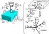 |
Figure 3. The mass-spring vibratory model of the coupled “spindle-workpiece-fixture” system. |
As shown in Figure 4, the workpiece structural compliance at the fixture-workpiece contact is approximated by three linear springs and is incorporated into the overall of the system by placing them in series with other springs representing the contact and fixture element compliances.
 |
Figure 4. Composite stiffness at the ith fixture-workpiece contact. |
2.4 Calculation of the fixture-workpiece stiffness
The calculation of the local stiffness of the fixture-workpiece system is given by this equation [27, 30]:![Mathematical equation: $$ {k}_{{ij}}={\left[({k}_{{ijf}}{)}^{-1}+({k}_{{ijc}}{)}^{-1}+({k}_{{ijw}}{)}^{-1}\right]}^{-1}. $$](/articles/smdo/full_html/2014/01/smdo130005/smdo130005-eq28.gif) (13)
(13)
The spring constants for the workpiece structural stiffness (kixW, kiyW and kizW for i = 1–8) are obtained using a finite element (FE) method. The fixture-workpiece contact stiffness, kijc can be obtained by this equation [27]: (14)where
  , υ, E and G represent the Poisson’s ratio, Young’s modulus, and shear modulus of the material, respectively.
A fixture element (locator or clamp) is modelled as a short or long cylindrical cantilever, depending on its length-to-diameter ratio. The structural stiffness of a fixture element is calculated by the following expression [27]: (15)where Eif, Gif, Lif, Aif and Iif are the Young’s modulus, shear modulus, length, cross-sectional and polar moment of inertia of the ith fixture element, respectively.
2.5 Static model
The principle of minimum complementary energy [19, 20] is utilized to develop the static model so that it can deal with an arbitrarily configured fixture-workpiece system without suffering from static indeterminacy of problems. The static model is then essentially a constrained nonlinear optimization model. The objective function of the model is the total complementary energy of the fixture-workpiece system subjected to clamping forces, and the design variables are the unknown contact forces of the system. Since the structural compliance of the workpiece and fixture elements are considered to be negligible relative to the contact compliance, the total complementary energy of the system is given by the sum of the stress energy of the compressed nonlinear virtual springs used to model the contact stiffness. Note that only constant clamping forces generated by force-controlled fixture are considered in this study. Therefore, denoting Pi, Qxi, and Qyi as the contact forces due to clamping loads in the zi, xi, and yi directions, the static model can be written as:
Minimise Πc
 (16)
(16)
 (17)
(17)
 (18)
(18)
 (19)
(19)
 (20)
(20)
 (21)
(21)
The constraint (17) represents the static equilibrium condition; (18) results from the fact that constant clamping forces are used; (19) represents the Coulomb friction law; (20) comes from the unilateral nature of a fixture-workpiece contact; (21) represents the non-yielding constraint on the contact stress where Sy is the yield strength of the workpiece material while ai is the radius of the ith contact region and is a function of the normal force Pi. The forces are then substituted into the contact force-displacement relationship to calculate the contact elastic deformation due to clamping. The contact force-displacement relationship for a spherical-tipped fixture element pressed against a curved workpiece surface is given as follows [27]:![Mathematical equation: $$ {\delta }_z=\left[\frac{9{P}^2}{16R({E}^{\mathrm{*}}{)}^2}\right],\hspace{1em}{\delta }_j=\frac{{Q}_j}{8a}\left(\frac{2-{\upsilon }_w}{{G}_w}+\frac{2-{\upsilon }_f}{{G}_f}\right). $$](/articles/smdo/full_html/2014/01/smdo130005/smdo130005-eq38.gif) (22)
(22)
For j = x, y.
Where,  is the relative curvature at the contact with Rw being the local radius of the workpiece surface and Rf being the tip radius of the fixture element;
  , υ, E and G represent the Poisson’s ratio, Young’s modulus, and shear modulus of the material, respectively; the subscripts w and f refer to the workpiece and fixture elements, respectively;
  is the radius of the contact region.
2.6 Fixturing stability criteria
The dynamic stability of the fixtured workpiece during machining can be analyzed by determining the status of the interaction between the workpiece and fixture elements (i.e., locators and clamps) at each contact. Prior to machining, the clamps are actuated and this causes localized elastic deformation at the fixture-workpiece contacts. Consequently, the workpiece assumes a static equilibrium position, from which it undergoes dynamic motion during machining. Superposition of the static elastic deformation due to clamping and the dynamic displacement due to machining at a fixture-workpiece contact gives the total motion of that contact. As shown in Figure 5, three types of contact status are possible: full stick, macro-slip and lift-off. Since total restraint of the workpiece by the fixture must be satisfied throughout the machining operation, lift-off of the workpiece from any fixture element and macro-slip of the workpiece at any contact at any instant are indicators of an unstable workpiece. In the local coordinate system (xi
yi
zi) for the ith fixture-workpiece contact, lift-off is equivalent to a positive displacement of the workpiece in the zi direction while macro-slip indicates that the Coulomb friction law is violated. Therefore, the two fixturing stability criteria can be stated mathematically as in equation (23), which must be satisfied for i = 1 to (L + C) during machining.![Mathematical equation: $$ \begin{array}{l}\mathrm{max}\left\{{\Delta }_{{zi}}(t)\right\}\le 0\\ \mathrm{max}\left\{\sqrt{{\left[{k}_{{xi}}{\Delta }_{{xi}}(t)\right]}^2+{\left[{k}_{{yi}}{\Delta }_{{yi}}(t)\right]}^2}-{\mu }_s^i\left[{k}_{{zi}}\left|{\Delta }_{{zi}}(t)\right|\right]\right\}\le 0,\end{array} $$](/articles/smdo/full_html/2014/01/smdo130005/smdo130005-eq42.gif) (23)
(23)
 |
Figure 5. Dynamic contact interaction between workpiece and fixture element. |
where, t is the machining time;  ,
,  and
and  are the superposed displacements of the ith fixture-workpiece contact in the xi, yi, and zi directions, respectively;
  is the static friction coefficient at the ith contact; kxi, kyi, and kzi are the local contact stiffness’s in the xi, yi, and zi directions, respectively.
The total motion of the ith is obtained as follows: (24)where, symbols d and δ represent the dynamic and static displacements of the workpiece, respectively.
2.7 Optimization clamping forces methodology
The overall approach used in this article is to determine the minimum required clamping forces during machining is summarized in the flowchart shown in Figure 2. It is seen that the approach is based on the fixturing dynamic stability analysis procedure and an optimization method to perform the task of searching for the minimum set of clamping forces. Development of the clamping force optimization model is presented in the next section.
2.7.1 Nonlinear optimization model
The objective function to be minimized is the 2-norm of the clamping force vector Fc. The number of components of this vector depends on the number of clamps C used in the fixture and thus Fc ∈ Rc. The task here is to search in a C-dimensional hyperbox for Fc with minimum length that satisfies the stability conditions given by equation (23). This clamping optimization task is then formulated as a bi-level nonlinear programming problem as follows:
 (25a)
(25a)
 (25b)
(25b)
![Mathematical equation: $$ \mathrm{ma}{\mathrm{x}}_t\left\{\begin{array}{l}\sqrt{{\left[{k}_{{xi}}{\Delta }_{{xi}}(t)\right]}^2+{\left[{k}_{{yi}}{\Delta }_{{yi}}(t)\right]}^2}-\\ {\mu }_s^i\left[{k}_{{zi}}\left|{\Delta }_{{zi}}(t)\right|\right]\end{array}\right\}\le 0, $$](/articles/smdo/full_html/2014/01/smdo130005/smdo130005-eq51.gif) (25c)
(25c)
 (25d)where i = 1 to (L + C), Lb and Ub are the upper and lower bounds of Fc, respectively; δ is computed using equation (22) and the static optimization model given by equation (16).
This model includes two optimization tasks at two levels. The upper level is the minimization of the 2-norm of the clamping force vector and the lower level is the minimization of the total complementary energy of the fixture-workpiece system subjected to clamping forces. The constraint regions of the two optimization problems are implicitly dependent on each another.
2.7.2 Presentation of the PSO optimization model
PSO is an algorithm for finding optimal regions of complex search spaces through the interaction of individuals in a population of particles [28]. It was developed by Kennedy and Eberhart [29] based on the social behaviour metaphor.
This heuristic search algorithm is therefore used to solve equation (25)). The algorithm searches a solution space by adjusting the trajectories of individual vectors, called “particles” as they are conceptualized as moving points in multidimensional space. Each particle is assigned a randomized velocity. These particles are assigned velocities and are “flown” through the problem hyperspace. At the kth iteration, the best solution (pbestx) and the corresponding objective function value (pbest) that each particle has achieved so far are stored. Also stored is the index (gbest) of the particle that has the best performance in the group up to that iteration. Equations (26) and (27) are used to update the velocity (v) and the position (x) of the ith particle at the (k + 1)th iteration. (26)where w is the inertia weight; c1 and c2 are positive constants; rand and Rand are generators of random numbers between 0 and 1.
 (27)
(27)
3. Simulation example
A pocketing end milling simulation example is used to illustrate the approach developed in this paper for to verify the dynamic stability of a fixtured workpiece and to search the minimum set of clamping forces needed during machining. This example considers an end milling operation. As illustrated in Figure 6, the original workpiece is a solid block of aluminium 7075 and the operation involves milling a step cut on the top surface of the workpiece. The operation consists of 30 depth levels along the Z axis with 16 tool passes along the X axis at each level. The removed volume is about 23% of the total volume of the original workpiece.
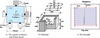 |
Figure 6. Final part and fixture layout (L1–L6: locators; C1–C2: clamps). |
Cutting conditions used in this example are given by the following Table 1.
Cutting conditions (tool: end mill, Ø 25.4 mm, 4-flute, and 30º helix).
The spatial coordinates of the fixture-workpiece contacts in the (xyz) frame are listed in Table 2. All fixture (clamps) elements are identical with a cylindrical body (radius = 20 mm and length = 30 mm) and a spherical tip (radius = 19.8 mm).
Coordinates of fixture-workpiece contacts
The material properties of the workpiece and the fixture elements are given in Table 3.
Material properties.
The instantaneous machining forces, shown in Figure 7 (during two tool revolutions), are obtained from a milling force model presented in this paper (derived from [22, 23]). Note that the effect of the helix angle on the cutting forces is neglected in the force model, resulting in a zero force in the Z direction. In general, the cutting force in the Z (axial) direction in milling is small especially for the small axial depth of cut (5 mm) and relatively small helix angle (30º) employed in the current example.
 |
Figure 7. Simulated milling forces. |
A modal analysis of the fixture-workpiece system was performed by the use of FEM for the initial and final workpiece geometries, and the first four natural frequencies are presented in Table 4. It can also be seen that the natural frequencies increase (become higher in the end of the milling operation) as the workpiece loses material.
Natural frequencies.
A spindle speed of 2500 rpm corresponds to tooth passing frequency 166.7, which is near the lowest natural frequency of the initial fixture-workpiece system 206, was finally selected for the example so as to disqualify a quasi-static analysis but not in the immediate vicinity of the peak areas to avoid resonance.
Figure 8 shows the convergence of the PSO search for the example machining operation. The two plots are for the first and last tool passes, respectively. The optimal clamping forces found for the two passes are given below the plots. The first observation confirms the search power of the PSO algorithm and the appropriateness of the values of design parameters listed in Table 5. The second observation indicates the significance of the material removal effect on the fixture-workpiece dynamics and consequently the minimum required clamping forces. It is suggests the need for time-varying clamping forces during machining.
 |
Figure 8. Convergence of the PSO search algorithm. |
Parameter values used in the PSO model.
Then the Figures 9 and 10 shows the fixturing dynamic stability of the system operating under the minimum required clamping forces simulated at the first and last pass. The horizontal axis of both plots in Figures 9 and 10 represents the fixture-workpiece contact indices which range from 1 to 8 corresponding to L1, L2, L3, L4, L5, L6, C1, and C2 (see Figure 6a), respectively. The vertical axes of plots in Figures 9 and 10 stand for the left hand sides of the two fixturing dynamic stability criteria (given in equation 23), respectively. Therefore, a stem above the zero horizontal line in Figures 9 and 10 is an indicator of lift-off or macro-slip at the corresponding fixture-workpiece contact. The height of a stem represents the degree of fixturing dynamic stability (if below zero) or instability (if above zero) of the contact. The Figures 9 and 10 illustrates that the two clamping forces simulated in the first and last pass are able to stabilize the workpiece during machining.
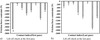 |
Figure 9. Lift-off check. |
 |
Figure 10. Macro-slip check. |
Note that the results of the convergence of the PSO search algorithm are:
-
For the first pass:
$](/articles/smdo/full_html/2014/01/smdo130005/smdo130005-eq55.gif) , i.e., Fc1 = 6830 N and Fc2=4330N.
, i.e., Fc1 = 6830 N and Fc2=4330N. -
For the first pass:
$](/articles/smdo/full_html/2014/01/smdo130005/smdo130005-eq56.gif) , i.e., Fc1 = 3843 N and Fc2 = 2180N.
, i.e., Fc1 = 3843 N and Fc2 = 2180N.
Figures 11–18 compare the dynamic motions of the fixture-workpiece system at the contact points during the first and last passes when their corresponding “minimum” clamping forces (see Figure 8) are used. It is seen that the dynamic motion of the fixtured workpiece (at the contact points) during the first tool pass is larger than during the last pass. This says that the workpiece experiences smaller motion as it loses material. The reason for this may be found by examining the change in the system natural frequencies as the material is cut away. The lowest natural frequency of the system is 206 Hz during the first pass and 252 Hz during the last pass. Although the change is not very large, the system inertia decreases significantly. The small change in the natural frequency is because the system stiffness also decreases as lower “minimum” clamping forces are used for the last pass. The dominant excitation frequency (i.e., tooth passing frequency) for this simulation example is 166.7 Hz, which is near the lowest natural frequency of the initial fixture-workpiece system. As the workpiece loses material, the machining operation moves away from resonance and thus produces smaller system dynamic motion.
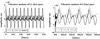 |
Figure 11. Dynamic motion at contact point L1 during the first and last depth level along Z. |
 |
Figure 12. Dynamic motion at contact point L2 during the first and last depth level along Z. |
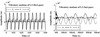 |
Figure 13. Dynamic motion at contact point L3 during the first and last depth level along Z. |
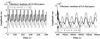 |
Figure 14. Dynamic motion at contact point L4 during the first and last depth level along Z. |
 |
Figure 15. Dynamic motion at contact point L5 during the first and last depth level along Z. |
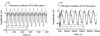 |
Figure 16. Dynamic motion at contact point L6 during the first and last depth level along Z. |
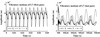 |
Figure 17. Dynamic motion at contact point L7 during the first and last depth level along Z. |
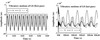 |
Figure 18. Dynamic motion at contact point L8 during the first and last depth level along Z. |
Note that workpiece motions (at the contact points) during only two tool revolutions are shown in each plot. As seen from these plots (Figures 11–18), the workpiece vibrations change significantly during the last pass in which 23% material has been removed. From the results, the key findings are as follows:
-
The fixture-workpiece system during the end milling operation presents significant dynamics when certain spindle speeds are used such that the excitation frequency is in the vicinity of a natural frequency of the system. In this scenario, consideration of the fixture-workpiece system dynamics is critical for an accurate analysis of the system.
-
Material removal in machining continuously changes the properties of the fixture-workpiece system, e.g., inertia and geometry. When a large portion of material is removed from the workpiece, the fixture-workpiece system behaves quite differently (in the example, the amplitudes of workpiece vibrations (at contact points) were found to be higher during the first tool pass than during the last pass). As a result, higher clamping forces are required to stabilize the workpiece during the first pass than during the last pass.
-
Because of the material removal effect, dynamic clamping is an option to achieve the best possible performance of a machining fixture-workpiece system. In addition, allowing different forces at different clamps with a good combination of the clamping forces can improve the overall fixture performance.
4. Conclusion
A systematic procedure for optimization of the clamped forces of a fixture-workpiece system in machining has been established in this paper. Through this study, it is seen that:
-
In determination of the minimum required clamping forces to ensure the fixturing dynamic stability of the fixture-workpiece system in the example milling operation, consideration of fixture-workpiece system dynamics is found to be crucial when the excitation frequency is in the vicinity of the natural frequency of the system.
-
Material removal significantly affects the fixture-workpiece system dynamics and subsequently the minimum clamping forces required for achieving fixturing dynamic stability. The minimum required clamping forces are found to decrease as material is removed from the workpiece.
-
Satisfaction of fixturing stability criteria requires good combinations of clamping forces, which can be determined from the model and approach developed in this paper.
Future research will focus on the influence of the structure compliance (for relatively flexible parts) on the stability of the fixtured workpiece.
References
- De Meter EC, Xie W, Choudhuri S, Vallapuzha S, Trethewey MW. 2001. A model to predict minimum required clamp preloads in light of fixture-workpiece compliance. International Journal of Machine Tools and Manufacture, 41, 1031–1054. [CrossRef] [Google Scholar]
- Kang Y, Rong Y, Yang JA. 2003. Geometric and kinetic model based computer-aided fixture design verification. Journal of Computing and Information Science in Engineering, Transactions of the ASME, 3, 187–199. [CrossRef] [Google Scholar]
- Meyer RT, Liou FW. 1997. Fixture analysis under dynamic machining. International Journal of Production Research, 5, 1471–1489. [CrossRef] [Google Scholar]
- Hurtado JF, Melkote SN. 2002. A model for synthesis of the fixturing configuration in pin-array type flexible machining fixtures. International Journal of Machine Tools and Manufacture, 42, 837–849. [CrossRef] [Google Scholar]
- Chen W, Ni L, Xue J. 2007. Deformation control through fixture layout design and clamping force optimization. International Journal of Advanced Manufacturing Technology, 38, 9–10, 860–867. [CrossRef] [Google Scholar]
- Zheng Y, Rong Y, Hou Z. 2008. The study of fixture stiffness-part I: a finite element analysis for stiffness of fixture units. International Journal of Advanced Manufacturing Technology, 36, 865–876, DOI:10.1007/s00170-006-0908-5. [CrossRef] [Google Scholar]
- Zheng Y, Hou Z, Rong Y. 2008. The study of fixture stiffness-Part II: contact stiffness identification between fixture components. International Journal of Advanced Manufacturing Technology, 38, 19–31. DOI:10.1007/s00170-007-1077-x. [CrossRef] [Google Scholar]
- Gui X, Fuh JYH, Nee AYC. 1996. Modeling of frictional elastic fixture-workpiece system for improving location accuracy. IIE Transactions, 28, 821–827. [Google Scholar]
- Li B, Melkote SN. 2001. Fixture clamping force optimization and its impact on workpiece location accuracy. The International Journal of Advanced Manufacturing Technology, 17, 104–113. [CrossRef] [Google Scholar]
- Vishnupriyan S, Majumder MC, Ramachandran KP. 2010. Optimization of machining fixture layout for tolerance requirements under the influence of locating errors. International Journal of Engineering, Science and Technology, 2(1), 152–162. [CrossRef] [Google Scholar]
- Wang YF, Wong YS, Fuh JYH. 1999. Off-line modeling and planning of optimal clamping forces for an intelligent fixturing system. International Journal of Machine Tools and Manufacture, 39, 253–271. [CrossRef] [Google Scholar]
- Tao ZJ, Kumar AS, Nee AYC. 1999. Automatic Generation of Dynamic Clamping Forces for Machining Fixtures. International Journal Production Research, 37(12), 2755–2776. [CrossRef] [Google Scholar]
- Liu JJ-X, Strong DR. 2003. Machining fixture verification for nonlinear fixture systems. International Journal of Advanced Manufacturing Technology, 21, 426–437. [CrossRef] [Google Scholar]
- Mittal RO, Cohen PH, Gilmore BJ. 1991. Dynamic modeling of the fixture-workpiece system. Robotics & Computer-Integrated Manufacturing, 8(4), 201–217. [CrossRef] [Google Scholar]
- Liao YG, Hu SJ. 2000. Flexible multibody dynamics based fixture-workpiece analysis model for fixturing stability. International Journal of Machine Tools & Manufacture, 40, 343–362. [CrossRef] [Google Scholar]
- Li B, Melkote SN. 2001. Optimal fixture design accounting for the effect of workpiece dynamics. The International Journal of Advanced Manufacturing Technology, 18, 701–707. [CrossRef] [Google Scholar]
- Kaya N, Öztürk F. 2003. The application of chip removal and frictional contact analysis for workpiece-fixture layout verification. International Journal of Advanced Manufacturing Technology, 21, 411–419. [CrossRef] [Google Scholar]
- Deng H, Melkote SN. 2006. Determination of minimum clamping forces for dynamically stable fixturing. International Journal of Machine Tools & Manufacture, 46, 847–857. [CrossRef] [Google Scholar]
- Bauchau OA. 2004. Aerospace Structural Analysis – Chapter 7: Variational and Energy Principles. Georgia Institute of Technology: Atlanta, USA. [Google Scholar]
- Li B, Melkote SN. 1999. Elastic contact model for the prediction of workpiece-fixture contact forces in clamping. Journal of Manufacturing Science and Engineering, Transactions of the ASME, 121(3), 485–493. [CrossRef] [Google Scholar]
- Mané I, Gagnol V, Bouzgarrou BC, Ray P. 2008. Stability-based spindle speed control during flexible workpiece high-speed. International Journal of Machine Tools & Manufacture, 48, 184–194. [CrossRef] [Google Scholar]
- Liu X, Cheng K, Webb D, Luo XC. 2002. Improved dynamic cutting force model in peripheral milling-Part 1: theoretical model and simulation. International Journal of Advanced Manufacturing and Technology, 20, 631–638. [CrossRef] [Google Scholar]
- Liu X, Cheng K, Webb D, Longstaff AP, Widiyarto HM, Jiang X-Q, Blunt L, Ford D. 2004. Improved dynamic cutting force model in peripheral milling-Part 2: Experimental verification and prediction. International Journal of Advanced Manufacturing and Technology, 24, 794–805. [CrossRef] [Google Scholar]
- Altintas Y, Budak E. 1995. Analytical prediction of stability lobes in milling. Annals CIRP, 44(1), 357–362. [CrossRef] [Google Scholar]
- Altintas Y. 2000. Manufacturing Automation: Metal Cutting Mechanics, Machine Tool Vibrations, and CNC Design. Cambridge University Press. [Google Scholar]
- Budak E, Altintas Y. 1998. Analytical prediction of chatter stability in milling; Part 1: General formulation, Part 2: Application of the general formulation to common milling systems. Journal of Dynamic Systems Measurement and Control, 120(1), 22–36. [CrossRef] [Google Scholar]
- Johnson KL. 1985. Contact Mechanics. Cambridge University Press: UK. [CrossRef] [Google Scholar]
- Clerc M, Kennedy J. 2002. The particle swarm-explosion, stability, and convergence in a multidimensional complex space. IEEE Transactions on Evolutionary Computation, 6, 58–73. [CrossRef] [Google Scholar]
- Kennedy J, Eberhart RC. 1995. Particle swarm optimization, in Proceedings of the IEEE International Conference on Neural Networks, vol. 4, Perth, Australia, IEEE Service Center, Piscataway, NJ. p. 1942–1948. [CrossRef] [Google Scholar]
- Jacobson B, Kalker JJ. 2000. Rolling Contact Phenomena. Springer: Wien, New York. p. 19–57. [Google Scholar]
Cite this article as: Chaari R, Abennadher M, Louati J & Haddar M: Mathematical methodology for optimization of the clamping forces accounting for workpiece vibratory behaviour. Int. J. Simul. Multisci. Des. Optim., 2014, 5, A13.
All Tables
All Figures
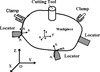 |
Figure 1. An arbitrary machining fixture-workpiece system [18]. |
| In the text | |
|
Figure 2. Procedure for optimization of the clamping forces. |
| In the text | |
|
Figure 3. The mass-spring vibratory model of the coupled “spindle-workpiece-fixture” system. |
| In the text | |
|
Figure 4. Composite stiffness at the ith fixture-workpiece contact. |
| In the text | |
|
Figure 5. Dynamic contact interaction between workpiece and fixture element. |
| In the text | |
|
Figure 6. Final part and fixture layout (L1–L6: locators; C1–C2: clamps). |
| In the text | |
|
Figure 7. Simulated milling forces. |
| In the text | |
|
Figure 8. Convergence of the PSO search algorithm. |
| In the text | |
|
Figure 9. Lift-off check. |
| In the text | |
|
Figure 10. Macro-slip check. |
| In the text | |
|
Figure 11. Dynamic motion at contact point L1 during the first and last depth level along Z. |
| In the text | |
|
Figure 12. Dynamic motion at contact point L2 during the first and last depth level along Z. |
| In the text | |
|
Figure 13. Dynamic motion at contact point L3 during the first and last depth level along Z. |
| In the text | |
|
Figure 14. Dynamic motion at contact point L4 during the first and last depth level along Z. |
| In the text | |
|
Figure 15. Dynamic motion at contact point L5 during the first and last depth level along Z. |
| In the text | |
|
Figure 16. Dynamic motion at contact point L6 during the first and last depth level along Z. |
| In the text | |
|
Figure 17. Dynamic motion at contact point L7 during the first and last depth level along Z. |
| In the text | |
|
Figure 18. Dynamic motion at contact point L8 during the first and last depth level along Z. |
| In the text | |
Current usage metrics show cumulative count of Article Views (full-text article views including HTML views, PDF and ePub downloads, according to the available data) and Abstracts Views on Vision4Press platform.
Data correspond to usage on the plateform after 2015. The current usage metrics is available 48-96 hours after online publication and is updated daily on week days.
Initial download of the metrics may take a while.