")
")
| Issue |
Int. J. Simul. Multidisci. Des. Optim.
Volume 16, 2025
|
|
|---|---|---|
| Article Number | 2 | |
| Number of page(s) | 10 | |
| DOI | https://doi.org/10.1051/smdo/2025001 | |
| Published online | 31 January 2025 | |
Research Article
Parameters analysis and process optimization of shell precision thermoforming
1
Shandong Jianzhu University, School of Materials Science and Engineering, Jinan 250101, China
2
Huazhong University of Technology, State Key Laboratory of Material Forming and Mould & Die Technology, Wuhan 430025, China
* e-mail: This email address is being protected from spambots. You need JavaScript enabled to view it.
Received:
9
November
2024
Accepted:
10
January
2025
Abstract
In this study, the aluminium alloy shell forming process is firstly studied and analysed. After that, the three-dimensional modelling software SOLIDWORKS is used to analyse and model the workpieces and the convex and concave dies of each process of the aluminium alloy shell hot extrusion forming process. Finally, the three-dimensional finite element numerical simulation software DEFORM-3D is used to carry out numerical simulation analysis on the precision hot forming process of aluminium alloy shell. Equivalent force and strain distributions, along with stroke-load curves, were analyzed under varying conditions by changing the friction factor and forming temperature. The simulation results show that under the conditions of friction factor of 0.25 and temperature of 450 °C, it is most suitable for the machining of aluminium alloy shell hot extrusion forming process.
Key words: Aluminum alloy shell / hot extrusion process / finite element method / numerical simulation
© H. Cheng et al., Published by EDP Sciences, 2025
 This is an Open Access article distributed under the terms of the Creative Commons Attribution License (https://creativecommons.org/licenses/by/4.0), which permits unrestricted use, distribution, and reproduction in any medium, provided the original work is properly cited.
1 Introduction
In recent years, with the rapid development of industrial technology, aluminum alloy shells are increasingly widely used in aerospace, automotive manufacturing and other fields [1–4]. Aluminum alloy shell has become a key material for improving equipment performance and reducing energy consumption due to its excellent properties such as light weight, high strength, corrosion resistance, good plasticity and toughness, and good fatigue resistance [5–8]. However, the hot extrusion forming process of aluminum alloy shell is a technically difficult machining process involving material properties, die design, process parameter optimization and other aspects. At present, scholars at home and abroad have carried out a large number of studies on the hot extrusion forming process of aluminum alloy shell, aiming to optimize the process parameters through numerical simulation, experimental validation and other means to improve the forming quality and production efficiency [9,10]. However, in the actual production process, there are still problems such as uneven stress distribution, insufficient forming accuracy, serious die wear, high cost of extruded profiles, and low mechanical properties, etc. [11–14], which limit the further development and application of aluminum alloy shell hot extrusion forming process.
In view of the importance of the aluminum alloy shell hot extrusion forming process and the existence of technical difficulties, this paper carries out an in-depth study. Through three-dimensional modeling and sectional analysis of 7A04-T6 aluminum alloy shell with a diameter of 155 mm, a set of forming scheme including primary punching, secondary punching, extrusion and tertiary punching was designed. On this basis, finite element numerical simulation of the hot extrusion forming process of aluminum alloy shell was carried out by using DEFORM software [15,16], to simulate the forming process under different temperatures and friction factors, respectively, and key data such as stress and strain distributions as well as stroke-load curves were obtained [17]. Through the analysis of the simulation results, revealed the influence of temperature and friction factor on the hot extrusion forming process of aluminum alloy shell, which provided a theoretical basis for optimizing the process parameters.
Aiming at the problems existing in the hot extrusion forming process of aluminum alloy shell, this paper adopts the method of combining numerical simulation and experimental verification for research [18]. First, through three-dimensional modeling and profile analysis, the structural characteristics and forming requirements of aluminum alloy shell were clarified, and a reasonable forming scheme and die structure were designed. Then, finite element numerical simulation was carried out using DEFORM software to explore the effects of temperature and friction factor on the forming process and optimize the process parameters. Finally, the simulation results were verified and corrected with experimental verification, and the most suitable temperature and friction factor for aluminum alloy shell hot extrusion forming process were obtained. This research result not only solves the technical problems in the aluminum alloy shell hot extrusion forming process, but also provides an effective method to improve the forming quality and production efficiency.
2 Experimental materials and methods
2.1 Material and process parameters
In this paper, the research material is 7A04-T6 aluminum alloy shell with a diameter of 155 mm, and its part drawing is shown in Figure 1.
According to the two-dimensional parts drawing using three-dimensional modeling software SOLIDWORKS for three-dimensional modeling. Continue to use three-dimensional modeling software SOLIDWORKS shell cut surface operation to get the shell section, as shown in Figure. Through the three-dimensional drawing as well as the sectional drawing in Figure 2, it can be clearly seen that the diameters of the through holes inside the shell are different and are divided into left and right part holes, with a protrusion in the left part of the center.
According to the analysis of three-dimensional modeling and sectional drawings, as well as the analysis of the hot extrusion forming process, the aluminum alloy shell under study is designed with the following forming scheme: primary punching → secondary punching → extrusion → tertiary punching. According to the scheme, the convex and concave dies for each process are designed and modeled.
A punching process to punch the small hole on the left side of the part figure, this hole is also used as a positioning hole in the following steps.
The blank used is shown in Figure 3, the size is determined according to SOLIDWORKS 3D modeling software for the final forming parts aluminum alloy shell modeling can be obtained forming parts volume of 1764944.2 mm3, so the volume of the blank is 1764944.2 mm3, the height of the blank to take 225 mm, the diameter of the blank is calculated to be φ99.94 mm, due to the final punch will be punched under the layer of thin material, so this paper selects the blank diameter of φ100 mm. Because the final punching will punch down a layer of thin material, so this paper chooses the blank diameter of φ100 mm.
The convex die used in this step is shown in Figure 4a, due to the consideration of punching force and the problem of deformation force of blanks, the front end of the convex die is selected as a bullet-shaped punch, in order to prevent the blanks from flowing out of the mold, the upper end of the convex die is used to widen the treatment of the concave die and the concave mold fit in the molding, so that the material in the gap between the convex-concave die flow molding. The diameter of this hole is φ66 mm, the length of the bullet of the convex mold is 50 mm, the maximum diameter is the same as the smallest part of the whole hole diameter of the shell is φ59 mm, the diameter of the cylinder above the bullet is the same as the diameter of the hole and the diameter of the hole on the lower side of the shell is φ66 mm. The diameter of the widened cylinder on the uppermost end is the same as the diameter of the opening of the concave mold and the diameter of the blank below, and the diameter of the blank is the same as φ100 mm. The concave mold cut-out used in the simulation is shown in Figure 4b. As shown in Figure 4b, the height of the blank will be increased when the blank is punched and extruded to prevent the blank from flowing out, so the height of the concave mold is chosen to be 288 mm plus 20 mm wall thickness, and the diameter of the opening is the same as the diameter of the blank of the convex mold, which is φ100 mm.
The secondary punching process punches the large hole on the right side of the part drawing, but since the concave die has a fixed part in this process, the premise of punching is to ensure that the convex and concave dies do not collide. This process is the next step in the extrusion process, so the purpose of this process is to punch out the upper end of the blank in the shape of a bowl, so that the next step in the extrusion process.
The convex die used in this step is shown in Figure 5a, due to the consideration of punching force and forming force, the convex die adopts a bullet-shaped punch for punching, similarly, in order to prevent the blank from flowing out during forming, the upper end of the convex die is widened, so that the blank can flow and form in the gap between the convex die and concave die. Because of the different diameters of the hole, the maximum diameter is φ157.7 mm, the minimum diameter is φ102 mm. Because of the concave die to locate the blank, in order to prevent collision between the locating parts and the convex die punches, so the design of the bullet punches with a length of 100 mm, the maximum diameter of φ75 mm. the purpose of this process is to punch the upper end of the blank into a bowl shape in order to the next step of the extrusion process smoothly. The cross-section of the concave die used is shown in Figure 5b, because one end of the blank was punched in the previous process, so in order to fix the blank in this process, a bullet-shaped fixing part is added at the low end of the concave die, which is the same as the punch in the previous process, and this part ensures the accuracy of the punching of the convex die in this process, but the convex die is also a bullet-shaped punch, and this process is to prevent the convex and concave dies from colliding. The internal shape of the concave die is the external contour of the case.
The extrusion process is to extrude the basic shape of the shell, leaving a thin layer of material in the middle part of the shell, which is punched down by the next punching process to get the final part aluminum alloy shell.
The convex die used in this process is shown in Figure 6a. The shape of the convex die is the internal contour of the final part of the aluminum alloy shell, which is designed according to the dimensions of the part drawing. To prevent the punch of the convex die from wearing out, the sharp corners are chamfered. Also, to prevent material from flowing out, the upper end of the convex die is widened so that the material flows in the gap between the convex die and the concave die. The convex die is widened to a maximum diameter of φ157.7 mm for the concave die. The cut surface of the concave die used is shown in Figure 6b, and the internal shape of the concave die is the same as that of the final piece of the shell case and is designed according to the dimensions of the part drawing. It is designed according to the dimensions of the parts drawing. At the low end of the concave die, there is a cylindrical fixed part that fills in the lower part of the shell, which plays the role of fixing and extrusion molding.
The third punching process punches down the thin layer of material left in the middle of the shell after extrusion molding. It is the last process of the hot extrusion forming process, and after obtaining the hot extruded parts, the final aluminum alloy shell can be obtained by simple machining of the parts. The convex die used is shown in Figure 7a, which is improved by the previous convex die by adding a punch with a diameter of φ59 mm at the front end, so that the thin material can be punched down to obtain the part.
The corresponding profile of the concave mould is shown in Figure 7b. The convex die has also been improved in the previous process by replacing the cylindrical fixing part under the concave die in the previous process with a cylindrical cylinder of thickness (66–59) ÷ 2 = 3.5 mm. It provides support and fixation as well as dropping the stamped scrap from the die.
 |
Fig. 1 Parts diagram. |
 |
Fig. 2 Parts diagram: (a) 3D modeling diagram, (b) sectional view. |
 |
Fig. 3 Blanks. |
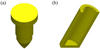 |
Fig. 4 Three-dimensional figure: (a) convex die for primary punching; (b) concave die for primary punching. |
 |
Fig. 5 Three-dimensional figure: (a) convex die for secondary punching; (b) concave die for secondary punching. |
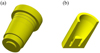 |
Fig. 6 Three-dimensional figure: (a) convex die in the third extrusion step; (b) concave die in the third extrusion step. |
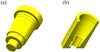 |
Fig. 7 Three-dimensional figure: (a) three times punching convex die; (b) three times punching concave die. |
2.2 Simulation process
Firstly, the finite element numerical simulation of aluminum alloy shell hot extrusion forming process is performed by DEFORM software. Aluminum alloy shell hot extrusion forming process has four hot extrusion forming processes, so the finite element numerical simulation process of hot extrusion forming process of the shell is divided into four simulation parts [19–22]. They are primary punching → secondary punching → extrusion → tertiary punching, and numerical simulations are performed for its four processes.
The finite element simulation model of the workpiece and the convex-concave die in the primary punching process is shown in Figure 8a, assuming that the billet is isothermally plastically deformed, the friction factor is taken as 0.25, and the temperature is 450 °C. The die is rigid without considering the deformation. The mold is a rigid body and deformation is not considered. The convex and concave molds and workpieces are positioned by object positioning so that they can be formed correctly. The upper die movement speed is taken as 10 mm/s and the downward pressure is 0.86 mm per step in the simulation. The different forming stages of the first punching process are shown in Figure 8b.
The finite element simulation model of the workpiece and the convex-concave die in the secondary punching process is shown in Figure 9a. It is assumed that the blank is isothermal plastic deformation, the friction factor is taken as 0.25, and the temperature is 450 °C. The mold is a rigid body and deformation is not considered. The convex and concave molds and workpieces are positioned by object positioning so that they can be formed correctly. The upper die movement speed is taken as 10 mm/s and the downward pressure is 0.72 mm per step in the simulation.The different forming stages of the second punching process are shown in Figure 9b.
The finite element simulation model of the workpiece and the convex-concave die in the extrusion process is shown in Figure 10a. It is assumed that the billet is isothermal plastic deformation, the friction factor is taken as 0.25, and the temperature is 450 °C. The mold is a rigid body and deformation is not considered. The convex and concave molds and workpieces are positioned by object positioning so that they can be formed correctly. The upper die movement speed is taken as 10 mm/s and the downward pressure is 0.60 mm per step in the simulation. The different forming stages of the third extrusion process are shown in Figure 10b.
The finite element simulation model of the workpiece and the convex-concave die in the three punching processes is shown in Figure 11a. It is assumed that the blank is isothermal plastic deformation, the friction factor is taken as 0.25, and the temperature is 450 °C. The mold is a rigid body and deformation is not considered. The convex and concave molds and the workpiece are positioned by object positioning so that they can be formed correctly. The upper die movement speed is taken as 10 mm/s and the downward pressure is 0.84 mm per step in the simulation. The different forming stages of the fourth punching process are shown in Figure 11b.
Finally the hot extrusion forming process was simulated by using DEFORM-3D software. The temperature and friction factor are controlled separately, and the material is analysed by equivalent force diagram, equivalent strain diagram and stroke-load curve. The temperature and friction factor that are most suitable for the hot extrusion forming process of aluminium alloy shell are finally obtained to provide theoretical basis for the actual production.
 |
Fig. 8 Simulation process: (a) one punch; (b) different stages of forming in one punch process. |
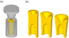 |
Fig. 9 Simulation of the process: (a) secondary punching; (b) different stages of forming in the secondary punching process. |
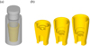 |
Fig. 10 Simulation of the process: (a) extrusion process; (b) different stages of forming in the extrusion process. |
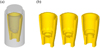 |
Fig. 11 Simulation of the process: (a) three punches; (b) different stages of the molding of the three punching processes. |
3 Results and discussion
Finite element analysis was performed using DEFORM software with the friction factor set to 0.25 and temperature as the only variable to investigate the stress distribution of the aluminum alloy shell at different temperatures. Figure 12 demonstrates the equivalent stress state of the shell at 400 °C, 450 °C and 500 °C, showing that the stress decreases with increasing temperature. However, obvious defects, such as cracks or property degradation, appear in the shell at 500 °C, affecting the mechanical properties and safety. This indicates that the design and application of materials in high-temperature environments need to fully consider the effects of temperature on material properties and structural integrity.
Further analysis of the equivalent strain diagram shown in Figure 13 reveals that although the change in temperature does not cause significant overall morphological differences in the distribution of equivalent strains in the forming process of aluminum alloy shells, it shows a certain pattern of change in the details. Specifically, under the condition of 400 °C, the degree of deformation of the shell is relatively small, which indicates that at this temperature, the fluidity and ductility of the material may have been restricted to a certain extent, making the strain accumulation in the forming process more limited. In contrast, when the temperature was increased to 500 °C, the deformation of the shells increased significantly, which may be attributed to the release of internal stresses and the enhancement of the fluidity of the material at high temperatures, resulting in a more susceptible to deformation during the molding process [23,24]. In contrast, at the intermediate temperature of 450 °C, the deformation of the shells shows a more ideal equilibrium. The results of this study are similar to those of Sun et al. [25]. It is neither too stiff to avoid molding difficulties due to insufficient material fluidity, nor too soft to prevent shape distortion or dimensional instability caused by excessive deformation [26]. This good performance of the degree of deformation helps to maintain the shape accuracy and dimensional consistency of the shell during the molding process, thus improving the quality and reliability of the final product. Afterwards, observing Figure 14, it is clear from the stroke-load curve that the load becomes smaller and smaller as the temperature increases.
Subsequently, when comparing the simulation results of the shell hot extrusion molding process under different friction factor conditions in Figure 15, it can be observed that the equivalent force plots do not exhibit significant differences in the overall trend. This observation initially suggests that the distribution of equivalent forces for the hot extrusion molding process may be stable and consistent over the range of friction factors examined. However, by carefully analyzing the simulation data at different friction factors, some key differences can still be found. Specifically, under the condition of friction factor of 0.4, the molding effect of the shell shows obvious defects. These defects may be in the form of stress concentration, non-uniform material flow or shape distortion during the forming process [27–29], which not only affect the overall forming quality of the shells, but also pose a potential threat to the subsequent use and performance of the shells. In contrast, the molding of shells under other friction factor conditions is relatively more desirable. Although the specific equivalent force distribution may vary depending on the friction factors, the overall molding quality and shape accuracy can be maintained.
Finally, by analyzing the equivalent strain plots for different friction factors in Figure 16 and the stroke load curves in Figure 17, a clear insight can be gained into the fact that the variation of the friction factor has an observable effect on the load when the temperature is kept constant during the hot extrusion molding of the shell. Specifically, as the friction factor gradually increases, the required load also shows a slightly increasing trend. This phenomenon suggests that the friction factor is an important factor that cannot be ignored in the hot extrusion forming process, and that it can influence the mechanical behavior and energy consumption of the forming process to a certain extent. At lower friction factor levels, the interaction between the shell and the die is relatively weak, the material flow is smoother, and therefore the required forming load is correspondingly smaller. However, as the friction factor increases, the friction between the shell and the mold increases, which leads to an increase in the resistance to be overcome during the molding process, and thus a slight increase in the required load.
Machining aluminium alloy housings at 450 °C with a coefficient of friction of 0.25 also presents potential problems of material degradation and equipment wear. Ye et al. [30] showed that higher temperature deformation leads to recrystallisation, which weakens the anisotropy of mechanical properties. At the same time, lubricants may fail at high temperatures, increasing friction and wear; tools may wear faster due to heat and friction; equipment components may deform, crack or even break due to thermal stresses; and aluminium alloys may adhere to tools or dies, making machining more difficult and costly. To reduce these risks, it is necessary to select aluminium alloy materials with high thermal stability and creep resistance, optimise machining parameters and processes, use lubricants suitable for high-temperature environments, regularly inspect and maintain equipment, and adopt advanced machining techniques and equipment.
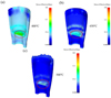 |
Fig. 12 Equivalent force diagrams for different temperatures: (a) 400 °C; (b) 450 °C; (c) 500 °C. |
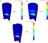 |
Fig. 13 Equivalent strain plots for different temperatures: (a) 400 °C; (b) 450 °C; (c) 500 °C. |
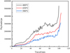 |
Fig. 14 Stroke-load curves for different temperatures |
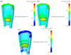 |
Fig. 15 Equivalent force diagrams for different friction factors: (a) 0.4; (b) 0.3; (c) 0.25. |
 |
Fig. 16 Equivalent strain diagrams for different friction factors: (a) 0.4; (b) 0.3; (c) 0.25. |
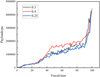 |
Fig. 17 Stroke-load curves for different friction factors. |
4 Conclusion
This study analyzes the forming process of aluminum alloy shells, models the workpiece and dies using 3D software, simulates the precision thermoforming process with simulation software, and finds optimal friction factor and temperature for hot extrusionand the following conclusions were drawn:
In the simulation of shell hot extrusion molding process, keeping the control friction factor unchanged, comparing the shell molding part diagrams, equivalent stress diagrams, equivalent strain diagrams and stroke-load curves at different temperatures, it can be learned that the stress and load are inversely proportional to the temperature.
By observing the shell forming part diagram, it can be seen that the degree of deformation is small at 400 °C, and the forming precision is insufficient; the degree of deformation is too large at 500 °C, and defects are produced; and the degree of deformation is moderate at 450 °C, and there are no obvious defects, and the precision is high. Therefore, the optimum temperature of aluminum alloy shell hot extrusion molding is 450 °C.
Keeping the optimum temperature of aluminum alloy shell hot extrusion molding for 450 °C unchanged, in the range of 0.25 to 0.4 friction factor, with the increase of the friction factor, the load also increases. It is recommended to minimize the friction during the extrusion process to improve the forming properties of the shell.
Acknowledgements
This study was supported by the National Natural Science Foundation of China, grant number 52105377 and the Key R&D Program of Shandong Province, China (2023TSGC0119).
Funding
This study was supported by the Key R&D Program of Shandong Province, China (2023TSGC0119).
Conflicts of interest
We declare that we do not have any commercial or associative interests that represent a conflict of interest in connection with the work submitted.
Data availability statement
Data will be made available on request.
Author contribution statement
Haozhe Cheng: Conceptualization, Methodology, Software, Validation, Formal analysis, Investigation, Data curation, Writing − Original Draft, Writing − Review and editing, Visualization. Shubo Xu: Resources, Supervision, Project administration, Funding acquisition, Writing − Review & Editing. Kangwei Sun: Investigation. Sheng liang Wang: Investigation. Yuefei Pan: Supervision. Hailong Ma: Supervision.
References
- X. Fan, B. Sun, W. Qu, X. Chen, X. Wang, Wrinkling and strengthening behaviors in the two-layer-sheet hot-forming-quenching integrated process for an Al-Cu-Mg-alloy thin-walled curved-surface shell, Materials (Basel) 16 (2023), https://doi.org/10.3390/ma161347661 [Google Scholar]
- M. Huang, Q. Zhou, J. Wang, S. Li, Die casting die design and process optimization of aluminum alloy gearbox shell, Materials (Basel) 14 (2021), https://doi.org/10.3390/ma141439992 [Google Scholar]
- F. Xia, H. Li, H.−g. Liu, B.−b. Zhao, Z.−q. Zhang, D.−h. Lu, J.−q. Chen, Forward hot extrusion forming process of 4-lobe aluminum alloy helical surface rotor, J. Central South Univ. 26, 2307–2317 (2019) [CrossRef] [Google Scholar]
- D. Kim, K. Park, M. Chang, S. Joo, S. Hong, S. Cho, H. Kwon, Fabrication of functionally graded materials using aluminum alloys via hot extrusion, Metals 9 (2019), https://doi.org/10.3390/met90202104 [Google Scholar]
- S. Sun, Y. Fang, L. Zhang, C. Li, S. Hu, Effects of aging treatment and peripheral coarse grain on the exfoliation corrosion behaviour of 2024 aluminium alloy using SR-CT, J. Mater. Res. Technol. 9, 3219–3229 (2020) [CrossRef] [Google Scholar]
- Q. Li, X. Zhang, L. Wang, J. Qiao, The effect of extrusion and heat treatment on the microstructure and tensile properties of 2024 aluminum alloy, Materials (Basel) 15 (2022), https://doi.org/10.3390/ma152175666 [Google Scholar]
- B. Wisner, A. Kontsos, Investigation of particle fracture during fatigue of aluminum 2024, Int. J. Fatigue 111, 33–43 (2018) [CrossRef] [Google Scholar]
- M. Araghchi, H. Mansouri, R. Vafaei, Y. Guo, Optimization of the mechanical properties and residual stresses in 2024 aluminum alloy through heat treatment, J. Mater. Eng. Perform. 27, 3234–3238 (2018) [CrossRef] [Google Scholar]
- G. Sun, S. Xiao, J. Wu, J. Zheng, J. Qin, Shaking table test and simulation on seismic performance of aluminum alloy reticulated shell structures under elastic and elastic-plastic stage, J. Build. Eng. 97, 110878 (2024) [CrossRef] [Google Scholar]
- D. Xiao, F. Yang, B.T. Le, S. Zhang, Modeling of piercing based on DEFORM-3D and the ensemble OSC-PLS-ELM method, IEEE Access. 6, 63537–63545 (2018) [CrossRef] [Google Scholar]
- S. Gneiger, N.P. Papenberg, A.R. Arnoldt, C.M. Schlogl, M. Fehlbier, Investigations of high-strength Mg-Al-Ca-Mn alloys with a broad range of Ca+Al contents, Materials (Basel) 14 (2021). https://doi.org/10.3390/ma1418543911 [CrossRef] [Google Scholar]
- X. Wang, D. Zhang, A. Li, D. Yi, T. Li, A review on traditional processes and laser powder bed fusion of aluminum alloy microstructures, mechanical properties, costs, and applications, Materials (Basel) 17 (2024). https://doi.org/10.3390/ma1711255312 [Google Scholar]
- W. Wang, J. Zhao, R. Zhai, A forming technology of spur gear by warm extrusion and the defects control, J. Manufactur. Process. 21, 30–38 (2016) [CrossRef] [Google Scholar]
- J.H. Kim, J.T. Yeom, J.K. Hong, S.Y. Shim, S.G. Lim, N.K. Park, Effect of scandium on the hot extrudability of 7075 aluminum alloy, Metals Mater. Int. 16, 669–677 (2010) [CrossRef] [Google Scholar]
- H. Zhao, Y. Cao, Y. Bai, H. Yao, C. Tian, Numerical simulation and tool parameters optimization of aluminum alloy transmission intermediate shell, Sci Rep. 14, 4241 (2024) [CrossRef] [MathSciNet] [Google Scholar]
- L. Jia, Y. Li, T. Hui, Y. Zhang, Numerical simulation and experimental research on microstructural evolution during compact hot extrusion of heavy caliber thick-wall pipe, Chin. J. Mech. Eng. 32 (2019), https://doi.org/10.1186/s10033-019-0316-z16 [Google Scholar]
- J. Jin, X. Wang, L. Deng, J. Luo, A single-step hot stamping-forging process for aluminum alloy shell parts with nonuniform thickness, J. Mater. Process. Technol. 228, 170–178 (2016) [CrossRef] [Google Scholar]
- J. Ma, Z. Han, A.K. Sachdev, A.A. Luo, The challenge and progress in macro- and micro-modeling and simulation of squeeze casting process, Metall. Mater. Trans. A (2024), https://doi.org/10.1007/s11661-024-07557-818 [Google Scholar]
- S. Wan, H. Su, B. Shao, Y. Zong, D. Shan, B. Guo, Changes in microstructure and mechanical properties of 2219 Al alloy during hot extrusion and post-extrusion aging, J. Mater. Res. Technol. 24, 3453–3463 (2023) [CrossRef] [Google Scholar]
- M.C. Santos, A.R. Machado, W.F. Sales, M.A.S. Barrozo, E.O. Ezugwu, Machining of aluminum alloys: a review, Int. J. Adv. Manufactur. Technol. 86, 3067–3080 (2016) [CrossRef] [Google Scholar]
- L. Li, R. Ma, J. Zhao, R. Zhai, Study on hot deformation behavior and bending forging process of 7075 aluminum alloy, Int. J. Precision Eng. Manufactur. 24, 729–744 (2023) [CrossRef] [Google Scholar]
- H. Ji, J. Qiao, N. Kang, X. Wang, J. Huang, Optimization of hot extrusion process parameters for 7075 aluminum alloy rims based on HyperXtrude, J. Mater. Res. Technol. 25, 4913–4928 (2023) [CrossRef] [Google Scholar]
- Z. Du, Z. Deng, X. Cui, A. Xiao, Deformation behavior and properties of 7075 aluminum alloy under electromagnetic hot forming, Materials (Basel) 14 (2021), https://doi.org/10.3390/ma1417495423 [Google Scholar]
- S.-H. Hsiang, J.-L. Kuo, An investigation on the hot extrusion process of magnesium alloy sheet, J. Mater. Process. Technol. 140, 6–12 (2003) [CrossRef] [Google Scholar]
- Y. Sun, Z. Cao, Z. Wan, L. Hu, W. Ye, N. Li, C. Fan, 3D processing map and hot deformation behavior of 6A02 aluminum alloy, J. Alloys Compd. 742, 356–368 (2018) [CrossRef] [Google Scholar]
- Z. Chen, G. Fang, J.-Q. Zhao, Formability evaluation of aluminum alloy 6061-T6 sheet at room and elevated temperatures, J. Mater. Eng. Performance 26, 4626–4637 (2017) [CrossRef] [Google Scholar]
- F. Li, H. Wu, M. Qin, Effects of processing parameters on the extrusion by continuous variable cross-section direct extrusion with 7A09 aluminium alloy, Mod. Phys. Lett. B 30 (2016), https://doi.org/10.1142/s021798491650053627 [Google Scholar]
- L. Zhao, K. Zhou, D. Tang, H. Wang, D. Li, Y. Peng, Experimental and numerical study on friction and wear performance of hot extrusion die materials, Materials (Basel) 15 (2022), https://doi.org/10.3390/ma1505179828 [Google Scholar]
- J. Gattmah, F. Ozturk, S. Orhan, Effects of process parameters on hot extrusion of hollow tube, Arab. J. Sci. Eng. 42, 2021–2030 (2017) [CrossRef] [Google Scholar]
- T. Ye, E. Xia, S. Qiu, J. Liu, H. Yue, J. Tang, Y. Wu, Deformation behavior of an extruded 7075 aluminum alloy at elevated temperatures, Materials 17 (2024), https://doi.org/10.3390/ma1705121030 [Google Scholar]
Cite this article as: Haozhe Cheng, Shubo Xu, Kangwei Sun, Shengliang Wang, Yuefei Pan, Hailong Ma, Guocheng Ren, Jianing Li, Zhongkui Zhao, Parameters analysis and process optimization of shell precision thermoforming, Int. J. Simul. Multidisci. Des. Optim. 16, 2 (2025), https://doi.org/10.1051/smdo/2025001
All Figures
|
Fig. 1 Parts diagram. |
| In the text | |
|
Fig. 2 Parts diagram: (a) 3D modeling diagram, (b) sectional view. |
| In the text | |
|
Fig. 3 Blanks. |
| In the text | |
|
Fig. 4 Three-dimensional figure: (a) convex die for primary punching; (b) concave die for primary punching. |
| In the text | |
|
Fig. 5 Three-dimensional figure: (a) convex die for secondary punching; (b) concave die for secondary punching. |
| In the text | |
|
Fig. 6 Three-dimensional figure: (a) convex die in the third extrusion step; (b) concave die in the third extrusion step. |
| In the text | |
|
Fig. 7 Three-dimensional figure: (a) three times punching convex die; (b) three times punching concave die. |
| In the text | |
|
Fig. 8 Simulation process: (a) one punch; (b) different stages of forming in one punch process. |
| In the text | |
|
Fig. 9 Simulation of the process: (a) secondary punching; (b) different stages of forming in the secondary punching process. |
| In the text | |
|
Fig. 10 Simulation of the process: (a) extrusion process; (b) different stages of forming in the extrusion process. |
| In the text | |
|
Fig. 11 Simulation of the process: (a) three punches; (b) different stages of the molding of the three punching processes. |
| In the text | |
|
Fig. 12 Equivalent force diagrams for different temperatures: (a) 400 °C; (b) 450 °C; (c) 500 °C. |
| In the text | |
|
Fig. 13 Equivalent strain plots for different temperatures: (a) 400 °C; (b) 450 °C; (c) 500 °C. |
| In the text | |
|
Fig. 14 Stroke-load curves for different temperatures |
| In the text | |
|
Fig. 15 Equivalent force diagrams for different friction factors: (a) 0.4; (b) 0.3; (c) 0.25. |
| In the text | |
|
Fig. 16 Equivalent strain diagrams for different friction factors: (a) 0.4; (b) 0.3; (c) 0.25. |
| In the text | |
|
Fig. 17 Stroke-load curves for different friction factors. |
| In the text | |
Current usage metrics show cumulative count of Article Views (full-text article views including HTML views, PDF and ePub downloads, according to the available data) and Abstracts Views on Vision4Press platform.
Data correspond to usage on the plateform after 2015. The current usage metrics is available 48-96 hours after online publication and is updated daily on week days.
Initial download of the metrics may take a while.