")
")
| Issue |
Int. J. Simul. Multidisci. Des. Optim.
Volume 8, 2017
|
|
|---|---|---|
| Article Number | A5 | |
| Number of page(s) | 9 | |
| DOI | https://doi.org/10.1051/smdo/2016013 | |
| Published online | 2017年2月09日 | |
Research Article
A novel substructure-based topology optimization method for the design of wing structure
1
Engineering Simulation and Aerospace Computing, Northwestern Polytechnical University, 710072
Xi’an, Shaanxi, P.R. China
2
Aircraft Strength Research Institute of China, 710065
Xi’an, Shaanxi, P.R. China
* e-mail: 该Email地址已收到反垃圾邮件插件保护。要显示它您需要在浏览器中启用JavaScript。
Received:
16
November
2016
Accepted:
17
November
2016
Abstract
The purpose of this paper is to demonstrate a substructure-based method dealing with the optimal material layout of the aircraft wing structure system. In this method, the topology optimization design domain of the aircraft wing is divided into multiple subordinate topological units which are called substructure. The material layout of each subordinate topology design unit is found for maximizing the total stiffness under a prescribed material usage constraint by using the Solid Isotropic Microstructures with Penalization (SIMP) method. Firstly, the proposed method is implemented to find the optimal material layouts of a high aspect-ratio I-beam. Different division ways and material constraints of the substructure have proven important influence on the total stiffness. The design formulation is applied to the optimization of an aircraft wing. Compared with the traditional one, the proposed method can find a reasonable and clearer material layout of the wing, especially material piled up near the fixed end is pushed toward the tip or the middle of the wing. The optimized design indicates the proposed method can enhance the guidance of topology optimization in finding reasonable stiffener layouts of wing structure.
Key words: Topology optimization / Substructure-based method / High aspect-ratio / Wing structure / Stiffener layouts
© Y. Zhao et al., published by EDP Sciences, 2017
 This is an Open Access article distributed under the terms of the Creative Commons Attribution License (http://creativecommons.org/licenses/by/4.0), which permits unrestricted use, distribution, and reproduction in any medium, provided the original work is properly cited.
1 Introduction
Topology optimization has been developed as an effective approach in figuring out the structure layout and saving structural weight during the conceptual design phase [1, 2]. Over the last few decades, researchers have provided various applications of the topology optimization to a variety of engineering disciplines [3]. Recently, the progress of topology optimization can be seen in some literature surveys [4–7] and the integrated layout design has become a tendency [8–10]. The achieved developments in the topology optimization have proven effective but suffered from a lot of challenges, especially in the light-weight design of the high performance aircraft and aerospace structure systems [11, 12]
One of the most important functional parts of an aircraft is its wing which bears serious loads such as self-weight, bending and torsion and even impact during the aircraft’s mission. The structure configuration of the wing will greatly influence the global performance and should be reasonably and efficiently designed.
On the one hand, the finite element model of the wing structure is transformed into a relatively simple one and most of the researches discussed the component of the wing structure. In the works of Vladimir and Raphael, the entire wing was discretized into a complex truss structure, and the optimum topology configuration of the wing structure was achieved by using the ground structure method [13]. Kurt and his coworkers [14] built the 3-D finite element model of a wing structure and a conceptual layout of the structure was obtained. A traditional energy based topology optimization method was applied to the wing-rib design in the works of Lars et al. [15]. For the conceptual design of the wing box, Qiu et al. [16] took the wing box as the object and realized the structural optimum design by finding out the load-transferred path. Wang [17] proposed a new ESO (evolutionary structure optimization) method based on a more appropriate rejection criterion, and gained the optimal layout of the structure of a flying wing with high aspect-ratio.
In some other papers, the layout design method of wing structure is divided into several steps. A bending criterion was introduced into the topology optimization process of a wing beam in the researches of Schramm and Zhou [18]. They analyzed the stability of the wing beam and gained a better design by using the practical hierarchical approach. Aiming to solve the layout optimization of the wing structure, Wang and Zhao [19] presented a two-stage approach to find the optimal numbers and locations of wing spars and determined the precise location of wing spars and the size of all wing components.
In the above mentioned works, there were few people search the structural layout with the whole wing structure and the traditional topology cannot be used directly in the engineering applications. For the topology optimization of a wing structure which is a typical long narrow structure system for maximum stiffness, the material always focuses around the fixed end and the tip or middle of the wing occupy no or a few materials and is always no clear if any. But the tip and middle of the wing need to bear the load from the skin and some other parts. Designers always have not that much guidance from the traditional topology optimization and it becomes difficult to decide the material layouts in this portions.
In this paper, to solve the above problem, the substructure-based method was proposed and implemented on the conceptual design of the wing structure. Here, the topological design domain of the whole wing was divided into several subordinate areas named topological units which are optimized by the Solid Isotropic Microstructures with Penalization (SIMP) [20–22] based topology optimization method. A topology optimization procedure is proposed to obtain the maximum total stiffness of the structure. The material usage of each topological unit is restricted between a prescribed range. Different division ways and material usage constraints of the topological units were discussed in Section 4. A typical wing structure was optimized by using the proposed method.
2 Basic definition of the substructure-based method
Most of the existing topology optimization methods set the material usage of the whole design domain as a constraint during the optimization procedure, especially in the stiffness optimization problems. The substructure-based method is proposed here to obtain a much more practical conceptual design. Considering a typical topology optimization of a structure system as shown in Figure 1, to obtain a maximum stiffness design, engineers often set an upper bound of the material usage volume fraction for the whole topology design domain. The material usage constraint condition of the traditional topology optimization can be written as: (1)where V is the material usage fraction of the topology design domain and
  stands for its upper bound.
 |
Figure 1. An illustration of the typical topology optimization. (a) Problem definition, (b) typical topology optimized design. |
Unfortunately, although the traditional optimization method can provide a relatively optimum objective, i.e. the maximum total stiffness of the system, of the problem, there exists many portions which should bear loads with a few or without any material in the design domain, especially on the topology optimization design of the high aspect-ratio structures, such as a long narrow beam as shown in Figure 2.
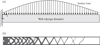 |
Figure 2. Illustration of the optimization of the web of a long narrow beam for maximum stiffness. (a) Load condition of the optimization problem, (b) optimization design of the problem. |
It is reasonable to gain the weak design in theory but not practical from the degree of the engineering applications. For the design of a high aspect-ratio aircraft wing, what the designers want is a robust or practicable configuration that can easily or directly guide the manufacture of the stiffeners’ layout. The proposed method divides the single topology design domain of the traditional method into several separated topological units as shown in Figure 3. Each unit marked from Unit 1 to Unit m has a corresponding material usage fraction constraint in the optimization procedure.
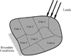 |
Figure 3. Illustration of the proposed substructure-based method. |
The material usage fraction constraints conditions of the proposed method can be written as: (2)
(2)
Where V j is the material usage of the j-th topological unit while V jL and V jU are its lower and upper bounds; m is the total number of the topological units of the structure. V represents the total material usage fraction of the system and V U stands for its upper bound.
By this means, the design domain is divided into several small topological units and each unit has a corresponding material usage fraction constraint. This formulation avoids it that the material focus around the fixed end of the topology optimization especially of the high aspect-ratio structure systems. And designers can readjust the material usage fraction of each unit to obtain a more practicable design. By adjusting the material usage constraints, there will be much more stiffeners locating near the tip or middle of the high aspect-ratio structure system. Designers can easily find a suggestive layout of the stiffeners compared with the traditional formulation. This will be discussed in the following section.
3 Optimization model
The objective of the optimization is to maximize the global stiffness of the structure system with several prescribed material usage fraction constraints of the topological units. The material usage fraction of each topological unit is restricted in a corresponding range while the total material usage of all the topology design domains should satisfy a prescribed fraction. The design variables are the pseudo-density variables which control the material distribution in each topological unit. The optimization model based on the proposed method can be mathematically elaborated as: (3)
(3)
Where x
i
is the pseudo-density design variable of the i finite element and n is the total number of the finite elements of the whole structure. C is the strain energy of the system.
K
and
u
are the global stiffness matrix and the global displacement vector, respectively;
f
is the nodal force vector of the structure system. A smaller value δ is introduced to avoid singularity during the calculation. The commonly used SIMP method is implemented in this paper. And the material interpolation formulation is expressed as (4)where E(i) is the Young’s modulus of the i-th finite element; p stands for the penalty factor in SIMP method. In this paper, p is set to be 4.
The sensitivities analysis for the pseudo-density design variables can be easily obtained and more detailed information can be found in Fletcher [23] and Vasiliev [24].
4 Numerical examples
In this section, some numerical examples are calculated to verify the proposed method. In Section 4.1, a typical high aspect-ratio model, i.e. a long narrow beam web is tested by the proposed formulation and some comparisons are made with the traditional method. In Section 4.2, we calculate a wing structure of a type of aircraft in engineering. Notice that the Globally Convergent Method of Moving Asymptotes (GCMMA) [25] within the Boss-QuattroTM optimization platform [26] is applied as the optimizer.
4.1 Topology optimization design of a high aspect-ratio I-beam with surface load
As we all known, most of the wing structure is narrow and long and it is always simply modeled with a high aspect-ratio beam. As displayed in Figure 4, a representative long narrow I-beam is discussed in this section. Here, the web of this beam is assigned as the topology optimization design domain and the ratio of L/h is 20; b is the flange of the beam and it is set as the non-design domain as marked in Figure 4. The size of this model L × h × b is 1.0 m × 0.05 m × 0.03 m. The material properties of the beam are: the elastic modulus E = 1.1 × 10¹¹ Pa and Poisson’s ratio v = 0.34.
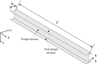 |
Figure 4. The geometry model of a cantilever beam with large aspect ratio. |
The load condition of this test is the same as Figure 5, and the aerodynamic load is applied on the top surface as a quadratic line with a maximum value 4 MPa and a minimum 0.2 MPa. The design domain is discretized into 22,011 shell elements and the left end of it is fixed in all directions.
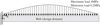 |
Figure 5. The load condition of the cantilever beam with large aspect ratio. |
Firstly, the problem is calculated using the traditional topology optimization and the material usage fraction of the whole web is assigned as a single constraint. The optimization is done for the maximum stiffness of the system. We change the upper bound of the material usage fraction from 0.25 to 0.45 stepping by 0.05 and obtain the final optimal design of these five conditions as shown in Table 1.
The optimal design of the beam under different material usage constraints.
From the above result, it can be seen that the traditional topology optimization method cannot deal the distribution of material in the web well. And there exists much redundant material near the fixed end. The results obtained in theory are not seems to be the practicable ones because there is no or few materials in the right or the center-right of the web while these portions are the very ones supporting the top and the bottom flanges of the beam.
Next, the proposed formulation is implemented to solve the same problem. The web is divided into topological units as shown in Figure 6.
 |
Figure 6. The division of the design domain using the proposed method. |
In Figure 6, the web is divided into 10 identical units marked from Ω1 to Ω10 and each unit need to be optimized within a prescribed material usage fraction constraint. The total material usage fraction of the structure is assigned as 0.45 which is the same as the no. 5 condition in Table 1. And in each topological unit, the material usage fraction is set between 0.10 and 0.50. Table 2 shows the comparison of the optimized designs by the proposed method and the traditional one.
Comparison of the optimized designs by the proposed method and the traditional one.
From the comparison, although the global strain energy increases by 6.25%, the proposed method can find a better layouts of the structure. In another sense, this method has a significance to increase the local stiffness and local performance by decreasing the global performance slightly. Compared with the traditional one, material distributed around the fixed end decreases and a clearer topology configuration is generated by using the proposed formulation. Stiffeners located at the center-right of the beam becomes stronger and this provides a significant guidance to the designers to remodel the configuration during the conceptual design phase.
Another important point is to find an optimal number or the division ways of the topological units. As for the above high aspect-ratio beam, we discuss the influence of different number of topological units. Generally, in the topology optimization, we expect to find an effective structure layout with an optimal stiffness. Here, we take the model shown in Figure 5 as the design system, and the size, properties and load conditions of the finite element model kept unchanged. We only change the number of the topological units. We chose nine equidistant finite elements located in the middle height of the web as the measurement elements and the strain energies of these elements basically illustrate the degree of the stiffness of the beam at the corresponding positions. The detailed definition of this is shown in Figure 7. The whole web is divided into m identical topological units marked from Ω1 to Ω m . And the material usage fraction constraints of each unit are set at the same range 0.10–0.50 with a total material usage fraction constraint 0.45.
 |
Figure 7. The detailed definition of the measurement method. |
As shown in Figure 8, the element strain energies at different positions vary with the number of m. It can be seen that when the number of m is 9, the smaller fluctuations is obtained and the strain energies of each measurement finite element is lower. We think this division will generate a better topology configuration.
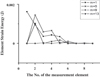 |
Figure 8. The illustration of element strain energy with different division ways. |
4.2 Topology optimization design of an aircraft wing structure
In this part, the proposed formulation is applied on the topology optimization design of an aircraft wing structure. Here, we divide the design domain of the wing into many basically different shape to find a better structure configuration for the engineering applications. The shape of topological units can be summarized into three types: type 1, according to the topology configuration obtained by the traditional topology optimization method, the airfoil is divided into many “radial” topological units; type 2, the fan-shaped topological units are introduced in order to scatter material from the root of the wing to the wingtip; type 3, the design domain is divided into several small block topological units. All the three types of topological units are shown in Figure 9. As shown in Figure 10, the configuration of the wing in the paper is similar to a trapezoid and a frame exists in the middle.
 |
Figure 9. The basic three types of topological units. (a) “Radial” topological units, (b) fan-shaped topological units, (c) block topological units. |
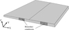 |
Figure 10 The geometrical model of the wing. |
The wing is fixed at its root at two local positions in all direction as shown in Figure 10. The applied aerodynamic load causes the displacement contour as shown in Figure 11. When the total material usage fraction constraint keeps a constant 0.30, the layouts of material obtained by the traditional topology optimization are mostly focused around the fixed ends as shown in Figure 12a and the paths of the material distribution is not that clear to guide the engineering applications significantly. Based on the previous proposed division ways as shown in Figure 9, we recalculate the same problem and the material usage fraction of each topological unit is restricted within a prescribed range 0.10–0.40 with a 0.30 total material usage fraction of the whole wing structure. The corresponding optimized configuration of different basic types of the topological unit is shown in Figures 12b–12d.
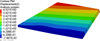 |
Figure 11. The displacement contour of the wing under the action of aerodynamic load. |
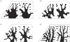 |
Figure 12. The corresponding optimized configuration of different basic types of the topological unit. (a) Traditional topology optimization, (b) optimized design of the “Radial” units, (c) optimized design of the fan-shaped units, (d) optimized design of the block units. |
It can be seen that when the design domain is divided into the radial-shape or the fanned-shape, material placed around the root seems not that stronger comparing with those in the middle of the wing. Moreover, material distributed around the tip or the leading and trailing edges is not sturdy enough to support the corresponding loads. In the block units design, the configuration is clearer than the above two. And the design shown in Figure 12d provides a significant guidance to designers to define the layouts of stiffeners in the wing.
From Figure 13, the stiffness of the design based on the fan-shaped unit is the best and close to the block unit. Combining the global strain energy and the configuration together, the material distribution is clearer with a proper stiffness when the shape of the topological unit is block and it is more helpful to find a better stiffeners’ layouts. This has proven effective of the proposed method.
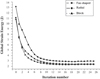 |
Figure 13. The global strain energy of different types of topological unit. |
In this section, we make some discussions about the influence caused by different material usage fraction constraints. Here, the wing is divided into several block topological units the same as the above test. Considering these two cases: case 1, i.e. the material usage fraction constraint of each topological unit has the same prescribed upper bound which is no more than the total fraction constraint and case 2, i.e. the material usage of each topological unit is set within a prescribed range of variability. The fraction of the total material usage is set to be 0.30 and the prescribed range of each topological unit is 0.10–0.40.
It can be seen from Figure 14 that when a range of variability of the material usage fraction is given, the maximum displacement of the design is decreased significantly comparing with the constant fraction. When the material usage constraint of each topological unit is limited below a given upper bound, the material distributed in the wing seems to be uniform in different topological units with a relatively higher strain energy. Although the stiffness of the design obtained by limiting the material usage within a range of variability is not the best, the configuration is the clearest among the three design results as shown in Figure 15. In other words, when the material usage of each topological unit is limited within a range of variability, material has much more freedom to find the better layouts. Designers and engineers are more inclined to the design with the clearest configuration to guide the engineering applications.
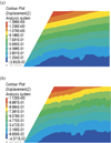 |
Figure 14. The displacement contour of the optimized design under the two different conditions. (a) The first case, (b) the second case. |
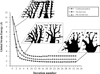 |
Figure 15. The global strain energy of different method. |
5 Conclusions
In this paper, a novel topology optimization method for the design of wing structure is proposed. In order to provide a better guidance for designers and engineers, a substructure-based method dealing with the optimal material layout of the whole aircraft wing structure system is implemented. By dividing the whole topology design domain into several subordinate topological units, the formulation is firstly applied to solve the topology optimization of a high aspect-ratio I-beam. By controlling the material usage fraction of each topological unit, a better design result is obtained comparing with the traditional topology optimization method. Compared with the traditional topology optimization method, material focused on the fixed end of the I-beam is pushed to distribute to the middle or the tip of the beam in some degree with a much clearer configuration. Secondly, the wing of an aircraft is optimized by the proposed formulation. The division ways and different material usage constraints of each topological unit are discussed in detail. We chose the block topological unit as the relatively better division of the wing and it is verified that when the material usage of each topological unit is limited within a given range, a better configuration will be generated compared with a limited upper bound of material usage of each unit. It has much freedom when the whole topology design domain is divided into several topological units with a material usage fraction constraint limited within a given range. The proposed method provides a significant guidance to designers and engineers in the engineering applications.
References
- Bendsøe MP, Sigmund O. 2003. Topology optimization: theory, method and applications. Springer-Verlag: Berlin, Heidelberg. [Google Scholar]
- Bendsøe MP, Kikuchi N. 1988. Generating optimal topologies in structural design using a homogenization method. Comput. Methods Appl. Mech. Eng., 71(2), 197–224. DOI: 10.1016/0045-7825(88)90086-2. [Google Scholar]
- Sigmund O, Maute K. 2013. Topology optimization approaches. Struct. Multidiscip. Optim., 48(6), 1031–1055. DOI: 10.1007/s00158-013-0978-6. [Google Scholar]
- Deaton JD, Grandhi RV. 2013. A survey of structural and multidisciplinary continuum topology optimization: post 2000. Struct. Multidisc. Optim., 49(1), 1–38. [CrossRef] [Google Scholar]
- Guo X, Cheng GD. 2010. Recent development in structural design and optimization. Acta Mech. Sin., 26(6), 807–823. [CrossRef] [MathSciNet] [Google Scholar]
- Zhu JH, Li Y, Zhang WH, Hou J. 2016. Shape preserving design with structural topology optimization. Struct. Multidiscip. Optim., 53(4), 893–906. DOI: 10.1007/s00158-015-1364-3. [CrossRef] [MathSciNet] [Google Scholar]
- Zhang WH, Zhu JH. 2006. A new finite-circle family method for optimal multi-component packing design. WCCM VII: Los Angeles. [Google Scholar]
- Zhu JH, Zhang WH. 2010. Integrated layout design of supports and structures. Comput. Methods Appl. Mech. Eng., 199(9), 557–569. DOI: 10.1016/j.cma.2009.10.011. [Google Scholar]
- Zhu JH, Zhang WH, Beckers P. 2009. Integrated layout design of multi-component system. Int. J. Numer. Methods Eng., 78(6), 631–651. DOI: 10.1002/nme.2499. [Google Scholar]
- Zhu JH, Gao HH, Zhang WH, Zhou Y. 2014. A multi-point constraints based integrated layout and topology optimization design of multi-component systems. Struct. Multidiscip. Optim., 51(2), 397–407. DOI: 10.1007/s00158-014-1134-7. [CrossRef] [Google Scholar]
- Zhu JH, Zhang WH, Xia L. 2016. Topology optimization in aircraft and aerospace structures design. Arch. Comput. Methods Eng.. DOI: 10.1007/s11831-015-9151-2. [Google Scholar]
- Remouchamps A, Bruyneel M, Fleury C, Grihon S. 2011. Application of a bi-level scheme including topology optimization to the design of an aircraft pylon. Struct. Multidiscip. Optim., 44(6), 739–750. [CrossRef] [Google Scholar]
- Vladimir B, Raphael H. 1994. Topology optimization or transport wing internal structure. 5th Symposium on Multidisciplinary Analysis and Optimization, American Institute of Aeronautics and Astronautics. [Google Scholar]
- Kurt M, Melike N, Charbel F. 2002. Conceptual layout of aeroelastic wing structures by topology optimization. 43rd AIAA/ASME/ASCE/AHS/ASC Structures, Structural Dynamics, and Materials Conference, American Institute of Aeronautics and Astronautics. [Google Scholar]
- Lars K, Alastair T, Martin K, Richard B. 2004. Topology optimisation of aircraft wing box ribs. 10th AIAA/ISSMO Multidisciplinary Analysis and Optimization Conference, American Institute of Aeronautics and Astronautics. [Google Scholar]
- Qiu FS, Ying P, Cong S, Liu ST. 2010. Topology optimization design of 3D wing box. Comput.-Integr. Manuf. Syst., 16(11), 2405–2409. [Google Scholar]
- Wang W. 2007. A new evolutionary structural optimization method and its application in the wing structure topology optimization. Aircraft Design. [Google Scholar]
- Schramm U, Zhou M. 2006. Recent developments in the commercial implementation of topology optimization, in IUTAM Symposium on Topological Design Optimization of Structures, Machines and Materials: Status and Perspectives. Bendsøe MP, Olhoff N, Sigmund O, Editors. Springer Netherlands: Dordrecht. p. 239–248. [CrossRef] [Google Scholar]
- Wei W, Zhao MY. 2008. Integrate topology/shape/size optimization into high aspect-ratio wing design. Journal of Mechanical Strength, 30, 596–600. [Google Scholar]
- Bendsøe MP. 1989. Optimal shape design as a material distribution problem. Struct. Optim., 1, 193–202. [CrossRef] [Google Scholar]
- Zhou M, Rozvany GIN. 1991. The COC algorithm, part II: topological, geometry and generalized shape optimization. Comput. Methods Appl. Mech. Eng., 89, 197–224. [Google Scholar]
- Mlejnek HP. 1992. Some aspects of the genesis of structures. Struct. Optim., 5, 64–69. [Google Scholar]
- Fletcher R. 1980. Practical methods of optimization 1. Vol. 1, John Wiley & Sons Ltd, Chichester, p71–94. [Google Scholar]
- Vasiliev OV. 1996. Optimization methods. World Federation Pub Inc. [Google Scholar]
- Svanberg K. 1995. A globally convergent version of MMA without linesearch. Proceedings of the first world congress of Struct Multidiscip Optim. Goslar, Germany, 28, 9–16. [Google Scholar]
- Radovcic Y, Remouchamps A. 2002. BOSS QUATTRO: an open system for parametric design. Struct. Multidiscip. Optim., 23(2), 140–152. [CrossRef] [Google Scholar]
Cite this article as: Zhao Y, Guo W, Duan S & Xing L: A novel substructure-based topology optimization method for the design of wing structure. Int. J. Simul. Multisci. Des. Optim., 2017, 8, A5.
All Tables
Comparison of the optimized designs by the proposed method and the traditional one.
All Figures
|
Figure 1. An illustration of the typical topology optimization. (a) Problem definition, (b) typical topology optimized design. |
| In the text | |
|
Figure 2. Illustration of the optimization of the web of a long narrow beam for maximum stiffness. (a) Load condition of the optimization problem, (b) optimization design of the problem. |
| In the text | |
|
Figure 3. Illustration of the proposed substructure-based method. |
| In the text | |
|
Figure 4. The geometry model of a cantilever beam with large aspect ratio. |
| In the text | |
|
Figure 5. The load condition of the cantilever beam with large aspect ratio. |
| In the text | |
|
Figure 6. The division of the design domain using the proposed method. |
| In the text | |
|
Figure 7. The detailed definition of the measurement method. |
| In the text | |
|
Figure 8. The illustration of element strain energy with different division ways. |
| In the text | |
|
Figure 9. The basic three types of topological units. (a) “Radial” topological units, (b) fan-shaped topological units, (c) block topological units. |
| In the text | |
|
Figure 10 The geometrical model of the wing. |
| In the text | |
|
Figure 11. The displacement contour of the wing under the action of aerodynamic load. |
| In the text | |
|
Figure 12. The corresponding optimized configuration of different basic types of the topological unit. (a) Traditional topology optimization, (b) optimized design of the “Radial” units, (c) optimized design of the fan-shaped units, (d) optimized design of the block units. |
| In the text | |
|
Figure 13. The global strain energy of different types of topological unit. |
| In the text | |
|
Figure 14. The displacement contour of the optimized design under the two different conditions. (a) The first case, (b) the second case. |
| In the text | |
|
Figure 15. The global strain energy of different method. |
| In the text | |
Current usage metrics show cumulative count of Article Views (full-text article views including HTML views, PDF and ePub downloads, according to the available data) and Abstracts Views on Vision4Press platform.
Data correspond to usage on the plateform after 2015. The current usage metrics is available 48-96 hours after online publication and is updated daily on week days.
Initial download of the metrics may take a while.