")
")
| Issue |
Int. J. Simul. Multidisci. Des. Optim.
Volume 13, 2022
|
|
|---|---|---|
| Article Number | 15 | |
| Number of page(s) | 8 | |
| DOI | https://doi.org/10.1051/smdo/2022005 | |
| Published online | 28 February 2022 | |
Research article
Design and analysis of shell and tube heat exchanger
School of Engineering and IT, Manipal Academy of Higher Education, Dubai Campus 345050, UAE
* e-mail: This email address is being protected from spambots. You need JavaScript enabled to view it.
Received:
16
June
2021
Accepted:
14
February
2022
Abstract
The demand for consumption of energy in industries has made designers to build efficient heat transfer exchangers. One of the most used heat exchangers which supports this is the shell and tube heat exchangers which are built for effective heat transfer. These heat exchangers are widely utilized in the HVAC industries especially in chiller plants due to their large surface for heat transfer. So, design of these chillers is influenced by the selection of material. This research paper discusses the design and analysis of shell and tube heat exchangers by considering different material and their ability to transfer heat from the surface. So, baffles play an important role to analyze the performance of the heat exchangers and it is possible to improve their heat transfer capabilities. So, in this research paper baffle spacing and its effect on heat transfer has been analyzed using CFD analysis and compared these results with the theoretical analysis. The Design and modelling of the heat exchanger have been modelled using PTC Creo parametric and using ANSYS Fluent CFD analysis have been carried out considering copper, aluminum, and steel as the materials. From this analysis it can be stated that copper has performed well as compared to aluminum and steel by using minimum baffle spacing.
Key words: Shell and tube exchanger / energy / baffle / steady state
© E.J. Fernandes and S.H. Krishanmurthy Published by EDP Sciences, 2022
 This is an Open Access article distributed under the terms of the Creative Commons Attribution License (https://creativecommons.org/licenses/by/4.0), which permits unrestricted use, distribution, and reproduction in any medium, provided the original work is properly cited.
1 Introduction
Heat exchangers are based on the principle of heat transfer taking place between the higher temperature fluid and the lower temperature fluid. Heat exchangers work by allowing the first fluid at a higher temperature to interact with the second fluid directly or indirectly at a lower temperature. This allows heat to transfer from the first to the second fluid, resulting in a reduction in the second fluid's temperature and an increase in the first fluid's temperature. Depending on whether heating or cooling is necessary, heat is transferred towards or away from the given system. Hence, in case of HVAC industries it is commonly used in air conditioning setups.
There is a wide array of research covered for shell and tube heat exchangers. Deshpande and Hinge [1] have studied the design and performance study of a single segmental shell and tube heat exchanger considering perpendicular and parallel baffle plates. They concluded that the perpendicular baffle cut orientation has great heat transfer rate as compared to parallel baffle plate cut while the pressure drop approximately remains the same. Gireesh and Rao [2] have studied the pressure drop inside the shell of a shell and tube heat exchangers considering different baffles using fluent software. They considered normal baffle, inclined baffle, and helical baffle for their study. They concluded that the helical baffle has performed well for effective pressure drop in case of shell and tube heat exchangers. Haran et al. [3] have studied thermal analysis in case of shell and tube heat exchangers considering both water and oil type which are most used in refrigeration and air conditioning industries. They developed a program using C for calculating thermal analysis considering counter flow in case of water oil type shell and tube heat exchangers. They concluded that using this program it is possible to study thermal analysis with least time and accuracy. Pranita et al. [4] have studied shell and tube exchangers by considering the effect of types of baffles considering thermal performance and pressure drop. They studied the numerical simulations on different baffles considering single, double, and helical baffles. They concluded that double segmental baffles reduce the vibrational damage to the system and helical baffles shows a decrease in pressure drop. Petinin and Dare [5] have studied the shell and tube heat exchangers considering different tube patterns variation like triangular, rotated triangular and the combined shell and tube heat exchangers. They concluded that triangular shell and tube heat exchangers is more desirable as they have more heat transfer coefficient for the same pressure drop. Arjun and Kaushik [6] have studied the optimal design in shell and tube heat exchangers considering various parameters such as outer diameter, pitch, length, baffle spacing and cut etc. They concluded that the designer need to take into consideration all these various parameters during designing to reduce the cost of the equipment. Young and Jee [7] have studied the performance of heat exchangers by changing fluid flow in the shell in case of shell and tube exchangers considering spiral baffle plates. They simulated a spiral baffle plate using thermal fluid analysis code. They concluded that using spiral baffle plate the heat exchanging capability is much superior as compared to conventional heat exchangers. Cahya and Permatasari [8] have studied shell and tube heat exchangers by comparing analytical calculations with simulation results using heat transfer research inc. They analyzed the quality of heat exchanger considering heat transfer coefficient considering contra flow to the hot fluid considering various flow rates. They concluded by plotting the various graphs of heat transfer coefficient on cold fluid flow considering number of tube and shell diameter. Amirtharaj et al. [9] have studied the shell and tube heat exchanger considering inclined baffles to achieve higher heat transfer efficiency and lower pressure drop. They compared using CFD analysis by considering segmental baffles with inclined baffles. They concluded that increased heat exchange and reduced pressure drop is achieved by segmental baffle as compared to inclined baffles. Oguz et al. [10] have studied thermal design of shell and tube heat exchangers using intelligent tuned harmony algorithm. They studied the design variables considering baffle spacing, shell diameter and tube diameters. They concluded that intelligent tuned harmony algorithm can be used to optimize shell and tube heat exchangers. Simin and Yanzhong [11] have studied heat transfer enhancement by installation of sealers in the shell side. They blocked the gap between the baffle plate and shell using sealers. They concluded that the heat transfer performance has improved and can be used for optimization of heat exchangers. Qiuwang et al. [12] have studied the combined multiple shell pass shell and tube heat exchangers using helical baffles to improve the heat transfer performance to simplify the manufacturing process. They studied the combined multiple pass shell with the conventional shell and tube heat exchanger with segmental baffles using CFD. They concluded that segmental baffles shell and tube heat exchanger have performed well in terms of energy saving, reduced cost and service life. From the literature review it is observed that lot of research have been performed in case of shell and tube heat exchanger considering segmental baffle, spiral baffle etc. to increase the heat transfer coefficient. The most common material used in case of baffles used in shell and heat exchangers are the carbon steel, alloy steel and non-ferrous materials. So, in this research work an attempt have been made to study shell and tube heat exchangers considering different materials such as stainless steel, aluminum, and copper.
2 Methodology
The effect of baffle spacing on a shell and tube heat exchanger have been studied and the effect of heat transfer rate when the baffle space is varied have been analyzed using Fluent in Ansys workbench. The shell and tube heat exchanger model are created using Creo Parametric and the analysis have been performed using Fluent in Ansys work bench. During this analysis it is assumed that ant fluid leak between tube and baffle is not considered, and shell side fluid is assumed to possess constant thermal properties and the heat exchanger is considered well insulated ((heat loss to the environment is totally neglected).
2.1 Design calculations
For design of shell and tube heat exchanger, Kern method [13,14] is employed which is most used in heat exchangers design. It offers a simple method for measuring heat transfer coefficient.
Log mean temperature difference (ΔTm) is calculated as,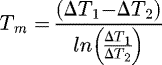 (1)
(1)
where ΔT1 = T1–t2 and ΔT2 = T2–t1 (T1, T2 = Inlet and outlet tube-side fluid temperature respectively (°C) and t1, t2 = Inlet and outlet shell-side fluid temperature respectively (°C)).
Heat transfer rate (Q), (2)where Q = Heat transfer rate (kJ/h), A = Heat transfer area (m2), ΔTm = Log mean temperature difference (°C), Uo = Overall heat transfer coefficient (W/(m2 K).
Based on above calculations the design of shell and tube heat exchangers dimensions are finalized.
Length of shell and tube heat exchanger (L) = 3 m, Outer diameter of shell and tube heat exchanger (Do) = 0.55 m, Area of shell and tube heat exchanger (A) = 5.105 m2, Heat transfer rate (Q= 298.203 kW, Inlet and outlet tube-side fluid temperatures, T1 = –1.12 °C and T2= 3.34 °C, Inlet and outlet shell-side fluid temperature, t1 = 12 °C and t2 = 7 °C, Overall heat transfer coefficient based on the fluids (Uo) = 480 W/(m2.K), Tube outer diameter (do) = 25 mm, Tube count (Nt) = 21 tubes, Tube pitch (Pt) = 80 mm (where C = clearance = 55 mm), Tube bundle diameter (Db) = 200 mm2 (where K1 = 0.215 and n = 2.207), Baffle pitch (bp) = 250 mm, Baffle cut (bc) = 25%, Number of baffles (bn) = 9 baffles.
3 Design of heat exchanger
3.1 Software modelling
A shell and tube heat exchanger was modelled in CAD software, Creo Parametric and the corresponding geometric specifications used is as follows. The design components modelled is shown in Figures 1 and 2 respectively.
 |
Fig. 1 Tube bundle and channel cover/tube-side nozzles. |
 |
Fig. 2 Baffle arrangement and final assembly with shell. |
3.2 CFD analysis
3.2.1 Geometry
Fluid model is created using Creo Parametric and created under Fluent in Ansys Workbench and is as shown in Figure 3.
 |
Fig. 3 Geometry. |
3.2.2 Meshing
A large mesh size created containing mixed cells (tetrahedral cell and hexahedral cell) with the shape of triangle and rectangle (refer Fig. 4). This was generated using automatic method which is available on ANSYS meshing client. Proximity is selected for sizing preference and coarse mesh is generated to get accurate results. 300 iterations were selected under hybrid initialization to get outlet of heat exchangers to obtain accurate results. To obtain converged solutions, X-Velocity, Y-Velocity, Z-Velocity, K-Epsilon should be below 10−4 and the energy below 10−7 for continuity have been selected. 600 iterations were used to obtain convergence.
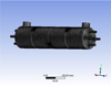 |
Fig. 4 Mesh model. |
3.2.3 Solution setup
Solution is setup under cell zone conditions and water selection is changed to fluid type. The simulation was carried out using Ansys Fluent software. The corresponding required material are selected from fluent material database and the calculation phase has been set for energy (to calculate heat transfer) by considering viscous realizable and standard wall. The boundary condition is set for velocity inlets and default temperature are specified for every tube inlet and for shell inlet.
3.2.4 Streamline plot
Within CFD-Post, required streamlines are plotted and results are obtained. The illustration of a temperature contour streamline along shell tube heat exchangers is demonstrated.
3.3 Steady state thermal analysis
To perform analysis for different materials, a simplified model of the heat exchanger is created with the help of Creo Parametric and is imported into Ansys Workbench under steady state thermal. Under engineering data, the required materials are selected from data source and coarse mesh is created and the corresponding loading conditions are entered, and materials are assigned for the various parts.
4 Results and discussion
4.1 Effect of baffle spacing
The effect of baffle spacing on the heat transfer rate is obtained from the analysis and tabulated as shown in Table 1. Figure 5 shows the temperature distribution contour for baffle spacing of 250 mm and 125 mm. From this figure it is observed that the maximum temperature in both the spacing is 5 × 10² k whereas the minimum temperature observed in case of 250 mm spacing is 3.474 × 10² k and 3.355 × 10² k for 125 mm baffle spacing. It is known that as the baffle space decreases the amount of heat transfer coefficient is more and pressure drop takes place whereas the baffle space increases the amount of heat transfer coefficient decreases and pressure drop increases. From this Figure 5 it is observed that a drop of 12 k is observed for baffle spacing between 250 mm and 125 mm and from Table 2 it is observed that the heat transfer coefficient is 76.68 W and 82.66 W and as per the previous literature there is more heat transfer taking place in case of 125 mm baffle spacing.
Figures 6a and 6b shows the convergence of simulation for bath baffle spacing of 125 mm and 250 mm. This convergence simulation in case of computational fluid dynamics [15–17] deals with fluid dynamics that involves non-linear processes like turbulence, convergence etc. Convergence is required to improve accuracy of solution through iterations to find solution as close to exact solution. Similarly Figures 7a and 7b shows the turbulent kinetic energy versus position graph for baffles of 125 mm and 250 mm. From this figure it is observed that there are steep rise and fall of turbulent kinetic energy and is due to presence of baffles within the heat exchanger. There is a rise in kinetic energy of the fluid as it passes around the baffles. Also, more turbulence is observed due to smaller baffle spacing in case of Figure 7a. There is a less turbulence in case of 250 mm baffle spacing as compared to 125 mm baffle spacing and is occurring due to baffle spacing.
Figure 8a shows the temperature observed for shell which is made of stainless steel [18,19] and baffles made of aluminum. From this Figure 8(a) it is observed that the maximum temperature is 12.013 degree centigrade, and the minimum temperature observed is 3.23 degree centigrade. Figure 8b shows the temperature observed for shell and baffles made of aluminum. From this Figure 8b it is observed that the maximum temperature is 10.889 degree centigrade and minimum temperature of 3.208 degree centigrade. Also, from Table 3 it is observed that for stainless steel shell and aluminum baffles the heat transfer rate is 0.63396 W/m2 whereas for aluminum shell tubes, and baffles the heat transfer rate is 0.73216 W/m2. From this it is observed that aluminum shell and baffles have better heat transfer capability as compared to stainless steel shell and aluminum baffles.
Figure 9a shows the temperature for stainless steel shell and copper baffles [20]. From this Figure 9a it is observed that the maximum temperature is 12.044 degree centigrade and minimum temperature observed is 3.281 degree centigrade. Similarly, Figure 9b shows the temperature for shell and baffles made of copper material and the maximum and minimum temperature observed is 8.844 degree and 3.253 degree centigrade. Also, from Table 3 it is observed that maximum heat flux is 0.88990 W/m2 in case of stainless-steel shell and copper baffles whereas the maximum heat flux is 1.236 W/m2 in case of copper tube and baffles. From this it is observed that copper tube and baffle have performed better as compared to stainless steel shell and copper baffle which in turn increases the heat transfer. Figure 10a shows the temperature for shell and baffles made of stainless steel and from this Figure 10a it is observed that the maximum and minimum temperature is 12 degree and 3.090 degree centigrade. Similarly, from Figure 10b it is observed that the maximum temperature and minimum temperature observed is 10.35 degree and 3.213 degree centigrade for shell and baffle made of aluminum and copper. From Table 3 it is observed that the heat flux for stainless steel shell and aluminum baffle is 0.63396 W/m2 whereas for shell made of aluminum [21] and baffles made of copper is 0.71455 W/m2. From this it is observed that aluminum shell and copper baffle have performed better as compared to stainless steel shell and baffle.
From this analysis it is stated that copper tube and baffle have performed well as compared to stainless steel and aluminum and has higher rate of heat transfer as compared to other material. Also, reduction in baffle space results in higher heat transfer capability by creating more turbulence was obtained during CFD approach in Ansys Fluent software. From this it can be stated that baffle spacing should be kept minimum to allow heat transfer however, baffles play an important role in providing support, they should be placed far enough to offer support to the shell and reduce the risk of damage by vibrations.
This analysis has been performed by considering aluminum, steel, and copper as the material. To enable good heat transfer for a long period of time, material selection plays an important role. This material selected should have good thermal conductivity in tube material to transfer the heat effectively. Poor choice of material selection will lead to leak causing fluid mixing and pressure loss.
Geometrical specifications.
 |
Fig. 5 Temperature Distribution contour for 250 mm and 125 mm baffle pitch. |
Effect of baffle spacings.
 |
Fig. 6 (a) and (b) Convergence of simulation (Baffle spacing of 125 mm and 250 mm). |
 |
Fig. 7 (a) and (b) Turbulent kinetic energy vs. Position graph for baffles of 125 mm and 250 mm. |
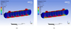 |
Fig. 8 (a) Temperature for shell (Stainless Steel), tubes and baffles (Aluminum) (b) Temperature for shell (Aluminum), tubes and baffles (Aluminum). |
Effect of materials utilized on heat exchanger.
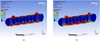 |
Fig. 9 (a) Temperature for shell (Stainless Steel), tubes and baffles (Copper) (b) Temperature for shell (Copper), tubes and baffles (Copper). |
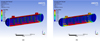 |
Fig. 10 (a) Temperature for shell (Stainless Steel), tubes and baffles (Stainless Steel) (b) Temperature for shell (Aluminum), tubes and baffles (Copper). |
5 Conclusion
In this research paper, shell and tube heat exchanger are modelled using Creo parametric and analysis have been performed using Ansys fluent. This analysis has been performed by considering baffle spacing after creating a simple model. Steady state thermal analysis using Ansys workbench have been performed by shell and baffles made of various material such as stainless steel, copper, and aluminum. From this study the following conclusion were made.
Baffle spacing place a significant role in the heat transfer rate in case of shell and tube heat exchangers.
The selection of the material has a significant impact on heat transfer rate in case of shell and tube heat exchangers.
From this research study it can be concluded that shell and baffles made of copper has performed better as compared to stainless steel and aluminum. However, due to high cost, copper cannot be used for all parts of shell and tube boiler but can be used as baffles. Also, copper has moderate corrosion resistance but tends to discolor easily. In these cases, aluminum would be the next best option as it is lightweight.
Notations
l: Length of model (mm)
ΔTm: Log-mean temperature difference (°C)
cp: Specific heat of fluid (J/kg °C)
A: Heat transfer area (m2)
T1 : Inlet tube side fluid temperature (°C)
T2 : Outlet tube side fluid temperature (°C)
t1 : Inlet shell side fluid temperature (°C)
t2 : Outlet shell side fluid temperature (°C)
U: Overall heat transfer coefficient (W/m2 °C)
Q: Heat transfer rate (kW)
bp: Baffle pitch (mm)
bc: Baffle cut (%)
Nt: Number of tubes
Pt: Tube pitch
nS: Number of tube passes
K1, n1 : Constants depending on the pitch and type of pass
Ea: Evaporator approach temperature (°C)
Tlcw: Leaving chilled water temperature (°C)
c: Clearance (mm)
bn: Baffle number
D: Diameter of shell (mm)
d: Diameter of tubes (mm)
Db: Tube bundle diameter (mm)
References
- S.S. Deshpande, S.A. Hinge, Design and performance study of shell and tube heat exchanger with single segmental baffle having perpendicular & parallel-cut orientation, Int. J. Eng. Res. Technol. 3, 1–5 (2014) [Google Scholar]
- D. Gireesh, J.B. Rao, Design and analysis of heat exchanger with different baffles, Int. J. Mag. Eng. Technol. Manag. Res. 4, 1–12 (2017) [Google Scholar]
- V. Hari Haran, G. Ravindra Reddy, B. Sreehari, Thermal analysis of shell and tube heat ex-changer using C and Ansys, Int. J. Computer Trends Technol. 4, 1–6 (2013) [CrossRef] [Google Scholar]
- P. Bichkar, O. Dandgaval, P. Dalvi, R. Godase, T. Dey, Proc. Manufactur. 20, 195–200 (2018) [CrossRef] [Google Scholar]
- M.O. Petinin, A.A. Dare, Performance of shell and tube heat exchangers with varying tube layouts, Br. J. Shell Tube Heat Exchangers Varying Tube Layouts 12, 1–8 (2016) [Google Scholar]
- A.K. Prasad, K. Anand, Design and analysis of shell and tube type heat exchanger, Int. J. Eng. Res. Technol. 9, 524–539 (2020) [Google Scholar]
- Y.-S. Son, J.-Y. Shin, Performance of a shell-and-tube heat exchanger with spiral baffle plates, KSME Int. J. 15, 1555–1562 (2001) [CrossRef] [Google Scholar]
- A.H. Cahya, R. Permatasari, Design of shell and tube heat exchanger for waste water using heat transfer research inc, Int. J. Adv. Sci. Technol. 29, 611–622 (2020) [Google Scholar]
- P.S.P. Amirtharaj, S. Allaudinbasha, M. Janagan, R. Karthikeyan, S. Muthukumar, Design and analysis of shell and tube heat exchanger with inclined baffles, Int. J. Sci. Eng. Dev. Res. 1, 252–260 (2016) [Google Scholar]
- O.E. Turgut, M.S. Turgut, M.T. Coban, Design and economic investigation of shell and tube heat exchangers using improved intelligent tuned harmony search algorithm, Ain Shams Eng. J. 5, 1215–1231 (2014) [CrossRef] [Google Scholar]
- S.W. Wen, Y. Li, An experimental investigation of heat transfer enhancement for a shell-and-tube heat exchanger, Appl. Thermal Eng. 29, 2433–2438 (2009) [CrossRef] [Google Scholar]
- Q. Wang, Q. Chen, G. Chen, M. Zing, Numerical investigation on combined multiple shell-pass shell-and-tube heat exchanger with continues helical baffles, Int. J. Heat Mass Transfer 52, 1214–1222 (2009) [CrossRef] [Google Scholar]
- M. Alpaslan, A. Erhan Kayabasi, H. Kurt, Detailed comparison of the methods used in the heat transfer coefficient and pressure loss calculation of shell side of shell and tube heat exchangers with the experimental results, Energy Sources A (2019) DOI: 10.1080/15567036.2019.1672835 [Google Scholar]
- H. Bayram, G. Sevilgen, Numerical investigation of the effect of variable baffle spacing on the thermal performance of a shell and tube heat exchanger, Energies 10, 1156 (2017) [CrossRef] [Google Scholar]
- E. Pal, I. Kumar, J.B. Joshi, N.K. Maheshwari, CFD simulations of shell side flow in a shell-and-tube type heat exchanger with and without baffles, Chem. Eng. Sci. 143, 314–340 (2016) [CrossRef] [Google Scholar]
- U. Ur Rehman, Heat transfer optimization of shell-and-tube heat exchanger through CFD studies, Master's thesis in innovative and sustainable chemical engineering. Chalmer's University of Technology, Sweden (2011) [Google Scholar]
- J.-F. Zhang, Y.-L. He, W.-Q. Tao, 3D numerical simulation on shell-and-tube heat exchangers with middle-overlapped helical baffles and continuous baffles − Part I: Numerical model and results of whole heat exchanger with middle-overlapped helical baffles, Int. J. Heat Mass Transfer 52, 5371–5380 (2009) [CrossRef] [Google Scholar]
- V. Kumar, G. Karnajothi, M. Saravanan, Effects of baffles and tube materials in the shell and tube heat exchangers using computational fluid dynamics, Int. J. Appl. Eng. Res. 10, 29653–29657 (2015) [Google Scholar]
- A. Ali, A. Mohammed, Q. Kareem, S. Zaki Naji, Performance analysis of shell and tube heat exchanger: parametric study, Case Stud. Thermal Eng. 12, 563–568 (2018) [CrossRef] [Google Scholar]
- N. Krishnan, M. Suresh, B. Kumar, An overview on shell and tube heat exchanger, Int. J. Eng. Sci. Comput. 6, 2632–2636 (2016) [Google Scholar]
- B. Buonomo, A. di Pasqua, D. Ercole, O. Manca, Numerical investigation on a heat exchanger in aluminum foam, Energy Proc. 148, 782–789 (2018) [CrossRef] [Google Scholar]
Cite this article as: Erica Jacqueline Fernandes, Sachidananda Hassan Krishanmurthy, Design and analysis of shell and tube heat exchanger, Int. J. Simul. Multidisci. Des. Optim. 13, 15 (2022)
All Tables
All Figures
|
Fig. 1 Tube bundle and channel cover/tube-side nozzles. |
| In the text | |
|
Fig. 2 Baffle arrangement and final assembly with shell. |
| In the text | |
|
Fig. 3 Geometry. |
| In the text | |
|
Fig. 4 Mesh model. |
| In the text | |
|
Fig. 5 Temperature Distribution contour for 250 mm and 125 mm baffle pitch. |
| In the text | |
|
Fig. 6 (a) and (b) Convergence of simulation (Baffle spacing of 125 mm and 250 mm). |
| In the text | |
|
Fig. 7 (a) and (b) Turbulent kinetic energy vs. Position graph for baffles of 125 mm and 250 mm. |
| In the text | |
|
Fig. 8 (a) Temperature for shell (Stainless Steel), tubes and baffles (Aluminum) (b) Temperature for shell (Aluminum), tubes and baffles (Aluminum). |
| In the text | |
|
Fig. 9 (a) Temperature for shell (Stainless Steel), tubes and baffles (Copper) (b) Temperature for shell (Copper), tubes and baffles (Copper). |
| In the text | |
|
Fig. 10 (a) Temperature for shell (Stainless Steel), tubes and baffles (Stainless Steel) (b) Temperature for shell (Aluminum), tubes and baffles (Copper). |
| In the text | |
Current usage metrics show cumulative count of Article Views (full-text article views including HTML views, PDF and ePub downloads, according to the available data) and Abstracts Views on Vision4Press platform.
Data correspond to usage on the plateform after 2015. The current usage metrics is available 48-96 hours after online publication and is updated daily on week days.
Initial download of the metrics may take a while.