")
")
| Issue |
Int. J. Simul. Multidisci. Des. Optim.
Volume 10, 2019
|
|
|---|---|---|
| Article Number | A2 | |
| Number of page(s) | 5 | |
| DOI | https://doi.org/10.1051/smdo/2019001 | |
| Published online | 12 March 2019 | |
Research Article
An example of design, optimization, stabilization and noise performances of resonator-based optoelectronic oscillators
Centre National de la Recherche Scientifique (CNRS), Franche Comté Electronique Mécanique Thermique Optique Sciences et Technologies (FEMTO-ST) Institute, Université de Bourgogne-Franche-Comté (UBFC), 15B avenue des Montboucons, 25030 Besançon, France
* e-mail: This email address is being protected from spambots. You need JavaScript enabled to view it.
Received:
29
August
2018
Accepted:
31
October
2018
Abstract
In this paper we talk about oscillators of optoelectronic type with intensity modulators and high-quality optical resonators technology. This subject is illustrated by an example of realization from the material to the characterization of the realized oscillator. It is explained how such an oscillator is designed and how it can be optimized.
Key words: Optoelectronic oscillator / optimization / resonator / frequency stability / phase noise measurement
© P. Salzenstein, published by EDP Sciences, 2019
 This is an Open Access article distributed under the terms of the Creative Commons Attribution License (http://creativecommons.org/licenses/by/4.0), which permits unrestricted use, distribution, and reproduction in any medium, provided the original work is properly cited.
1 Introduction
First optoelectronic oscillators (OEO) were developed in the United States [1]. There are some advantages with long delay lines oscillators. Their phase noise can be very low. Ten years ago, Eliyahu et al. [2] reached a phase noise of −163 dBc/Hz at 6 kHz offset from a 10 GHz carrier. The longer the delay line is, the lower the phase noise becomes, but a long delay line is more sensitive to temperature effect. It is a limitation for the phase noise performance. One of the challenges is to have a relatively compact system when designing an OEO. However, a resonator made of a crystal is a good candidate. But coupling a resonator to a line has to be performed accurately. Additionally, mechanical environment must be adequate. Having high Q-factor (quality factor) resonator aims specified goals such as low phase noise. Optimization signifies finding a way for the improvement of the OEO stability. It works at 1.55 µm. The stabilization of the optical frequency delivered by laser is essential. A technique is particularly used. It consists in Pound–Drever–Hall (PDH) [3]. We found that cells of TeO2 (paratellurite) crystal can be used as acousto-optic devices to stabilize a signal delivered in the microwave domain by an OEO. The system developed for the phase noise characterization of the microwave signal generated is then described.
2 A crystalline-resonator-based optoelectronic oscillator
2.1 Definitions and generalities
In this section, after a bit of history, we remind some important definitions.
John William Strutt (1842–1919) was known as Lord Rayleigh. He was an English physicist. He described origins and transmission of sound waves, and more precisely, phenomena of whispering-gallery-mode (WGM) resonance appearing in Saint Paul's Cathedral dome, located in the capital of England, in his book The Theory of Sound [4].
Similar to sound, light propagates by total reflection inside a WGM resonator. In case of an optical path, resonance is a multiple p of the wavelength λ: (1)
(1)
Thus, we remind several definitions.
Quality factor Q
OPT linked to photons lifetime (τ) inside the resonator is (2)where υ
OPT is the carrier frequency.
(2)where υ
OPT is the carrier frequency.
It means that (3)
(3)
The equivalent RF quality factor Q
RF is (4)where υ
RF is the microwave frequency.
(4)where υ
RF is the microwave frequency.
The free spectral range (FSR) determines the range of the microwave signal and is given by (5)
(5)
An evanescent field is created, which is useful for a possible coupling. Signal propagates inside the crystal resonator by total reflection. It is called WGM propagation for whispering gallery mode. To obtain a very long delay, the Q-factor of the resonator must be as high as possible. Microsphere [5] or disk resonators MgF2 [6], CaF2 [7] quartz and fused silica [8] give good results and each of them has advantages and limitations. To make a precise estimation of the quality factor, peaks are detected by cavity ringdown characterization [9]. When the quality factor is high enough, photon stays in the resonator for a longer period.
2.2 High-quality factor optical resonator
The radius of the resonator is typically 2.5–3 mm. It corresponds to the FSR around 10 GHz.
Grinding is the first step for making concretely the geometry for the guide. Silicon carbide is used for this. Stable table is necessary for avoiding defects due to geometrical variation. The speed at this step can be maximized. The speed is maximized, thanks to a very stable support and an air spinner motor. The next step consists in polishing to decrease roughness of the optical guide. Diamond is used as a powder with dimension less than 1 μm. Due to its hardness, every step needs more and more time. As a result, the full process has consequence that the roughness becomes low, down to 2 nm. That is why the quality factor becomes high [10].
2.3 Increasing the quality factor of the resonator
Realization of specific electronics and oven are described in references [11,12]. Oven is specially designed. The temperature is controlled. So the annealing is not too abrupt. It can then increase the Q-factor for photonics needs by relaxing the surface.
A cylindrical cavity is made of aluminum on its periphery. The muffle chamber is surrounded by a basalt fiber material and inserted inside the oven. Basalt is chopped. It is made of dry, woven noncrimp fabrics fibers. Fibers are milled. So it acts as a heat insulator and blocks fire. Wires are made of resistant alloy nichrome. The main benefit is to let the external surface of the resonator relax while current is passed through the wires.
2.4 Installation in OEO
We proceed as follows: In order to couple an optical disk resonator to the first tapered fiber, we proceed by searching the optimized position to produce absorption peaks as is shown in Figure 1a. Then we adjust the coupling position with a second one, as illustrated in Figure 1b, looking at the transmission peaks. Coupling can be optimized [10,13].
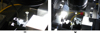 |
Fig. 1 Coupling process of a 5.5 mm disk resonator by tapered fibers. |
2.5 WGM resonators
Despite the best Q-factor up to 1011 corresponding to a photon lifetime of 100 μs has been achieved in an infrared regime by a team in the United States [14]. Quality factors of 109 have been achieved [9] with CaF2 or MgF2 using mechanical polishing. Modes propagate, thanks to dielectric structures. Modes are strongly confined inside the resonator while they propagate inside the crystal by total internal reflexion. Different shapes are investigated such as circular, spherical and toroidal, and their size is between few micrometers and few millimeters.
2.6 Experimental study of the realized OEO
Figure 2 schematizes the principle of OEO. The microwave amplifier compensates the losses in the resonator and the optoelectronic circuit to allow operation in oscillator mode. Note that the optical power delivered by the laser must not be too high (less than 20–40 mW according to the losses) to avoid nonlinearities. The imperfect flatness of the power delivered by the amplifier as a function of frequency, and the filtering elements, makes it possible to favor the emergence of a peak, which will be the microwave signal delivered by the oscillator. The circuit also has isolators to protect the low-noise microwave amplifier.
Fibers considered as through-port enable to obtain an optical spectrum using an optical spectrum analyzer. When there is no oscillation, working in open loop, through-port enables cavity ringdown characterization by sweeping a fast signal [15] and analyzes the detected signal, thanks to the oscilloscope. It can measure at the first optical output of the OEO by detection of an absorption peak. It enables to determine intrinsic and loaded Q-factor. MgF2 high-Q resonator were fabricated and characterized at Femto-St Institute in Besançon. Best Q-factors determined by cavity ringdown are between 109 and 1010 [16,17].
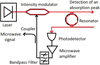 |
Fig. 2 Principle of OEO. Red color is used for optical signal and black for microwave signal. Optical signal transmitted through the resonator is detected by the photodetector. |
3 Stabilization of the laser
3.1 Pound–Drever–Hall stabilization
Microwave signal generated by the OEO presents instabilities due to temperature. There is a need to lock the laser on this microwave signal to follow the resonance. The most efficient way is to develop a PDH stabilization: the PDH technique is a largely used and powerful approach for stabilizing the wavelength of light emitted by a laser [3,18]. The main principle of PDH technique is to give an electric feed back to a laser: at the resonance condition, transition of phase can be converted to an error reference and is fed back to control frequency of laser. This approach is known to be a reliable one in the time domain. This PDH is typically applied in a number of various lasers: the linewidth is then smaller than the resonance linewidth. A frequency control parameter is also available. To understand how PDH works, please refer to a previous work [19].
3.2 Stabilization using acousto-optic cells
Principle of acousto-optic cells (AOC) is explained in references [20,21]. Choice of the range of frequency applied to the AOC is explained in reference [22]. The operation of the stabilized OEO consists in proceeding as follows: bulk acoustic waves are created from an error signal after the photodetector. Radio frequencies are between 55 and 65 MHz. A pair of quasi-identical cells provide the locking as required for the microwave signal detected after the photodiode. Concretely, with a Q-factor between 2 × 10⁷ and 2 × 10¹¹, the two radio frequencies vary from 2 kHz to 10 MHz. The 10 MHz maximum amplitude for those radio frequency signals should allow measuring resonators with relatively low Q-factor, especially better than 2 × 10⁷. It would be difficult to work with resonators with Q-factors less than 2 × 10⁷ because as detailed in reference [22], our AOCs only allow a 10 MHz difference between the two used signals at 55 and 65 MHz in that case. On the contrary, an ultrahigh quality factor at 1011 [14] requires a lower radio frequency difference of 2 kHz for driving the cells. AOCs are driven by two signals around 61 MHz. A synthesizer is used to change both frequencies. A numerically controlled oscillator is locked on a developed board for generating radio frequencies, as shown in Figure 3. The main advantage is the OEO stabilization. But there are potential limitations, such as difficulties when aligning two cells and inserting between laser and modulator.
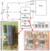 |
Fig. 3 Principle of the generation of RF signals. |
4 Phase noise measurements setup
4.1 Definitions
By definition, we can say that phase noise is like the power spectral density of the phase of one signal. Phase noise φ is given by (6)
(6)
The definition of phase noise is (7)where Sφ(f) is the one-sided spectral density of a phase shift of a signal, and f is the Fourier frequency. Despite Sφ(f) being one-sided function, it is called the double-sideband spectral density of phase fluctuation. Phase noise can be defined as the PSD in a 1 Hz band at a certain offset from the carrier.
4.2 Realized system
A signal generated by a microwave synthesizer enables the validation of performances for phase noise system. Optoelectronic system has double delay lines. It operates with a 1.55 µm wavelength laser. Cross-correlation enables a lower noise floor. To check validation of performances, comparison is performed between the phase noise datasheet of a commercial Anritsu synthesizer and the phase noise measured by the developed system. The noise floor of the system is then estimated. Noise floor of the instrument used for measuring is respectively determined as −170 dBc/Hz at 10 kHz and −90 dBc/Hz at 10 Hz from the 10 GHz carrier. Phase noise of the OEO is better than −125 dBc/Hz at 10 kHz from the microwave carrier. Uncertainty budget is determined according to GUM (Guide of Uncertainty Measurements). The global uncertainty is ±2 dB at 2σ with accredited calibration [23,24]. Recent works concur with Integrated OEO [25] with good results with resonator on chip and athermal waveguides applied to ring resonators [26].
5 Conclusion
Experimental results on an optoelectronic oscillator with intensity modulator and a high-Q minidisk resonator show that OEO based on a WGMR is relatively stable. It also shows that generated microwave signal presents a strong single peak in X-band. Phase noise of the realized OEO is better than −125 dBc/Hz at 10 kHz from the microwave carrier. Perspectives should consist in setting up a more accurate laser lightwave coupling, increasing the WGMR's loaded Q-factor and test on other miniature optical coupling designs such as prisms. It should lead to the achievement of lower phase noise levels. A promising work is the investigation in on-chip micro-resonators. Laser stabilization with AOCs is still to be investigated, but the main effort is still made on classical PDH technique as it proves its capabilities. Experimental results for 2 km delay line with cross-correlation method show the capability of the developed system to measure phase noise of oscillators up to −90 dBc/Hz at 10 Hz and −170 dBc/Hz at 10 kHz from a carrier in X-band frequency range. Measurement uncertainty is ±2 dB at 2σ and depends on the repeatability of the measure, it is ±0.68 dB at 1σ.
Acknowledgments
I acknowledge especially my colleague Mikhail Zarubin for his advice. This work was sponsored by Agence Nationale de la Recherche grant No. ANR2010BLAN031202, French foreign affairs and international development ministry (MAEDI) and Campus France grant No. 885706G 2016.
References
- X.S. Yao, L. Maleki, Optoelectronic microwave oscillator, J. Opt. Soc. Am. B 13, 1725–1735 (1996) [CrossRef] [Google Scholar]
- D. Eliyahu, D. Seidel, L. Maleki, Phase noise of a high performance OEO and an ultra low noise floor cross-correlation microwave photonic homodyne system, in Proceedings of the IEEE International Frequency Control Symposium, Honolulu, USA, May 19–21, 2008 [Google Scholar]
- R.W.P. Drever, J.L. Hall, F.V. Kowalski, J. Hough, G.M. Ford, A.J. Munley, H. Ward, Laser phase and frequency stabilization using an optical resonator, Appl. Phys. B 31 , 97–105 (1983) [NASA ADS] [CrossRef] [Google Scholar]
- J.W. Strutt, The theory of sound (Cambridge University Press, Cambridge, 1877) (print publication year: 2011; first published in 1877), ISBN: 9781139058087 [Google Scholar]
- A. Chiasera, Y. Dumeige, P. Féron, M. Ferrari, Y. Jestin, G. Nunzi Conti, S. Pelli, S. Soria, G.C. Righini, Spherical whispering-gallery-mode microresonators, Laser Phot. Rev. 4 , 457–482 (2010) [CrossRef] [Google Scholar]
- H. Tavernier, P. Salzenstein, K. Volyanskiy, Y.K. Chembo, L. Larger, Magnesium fluoride whispering gallery mode disk-resonators for microwave photonics applications, IEEE Phot. Tech. Lett. 22 , 1629–1631 (2010) [Google Scholar]
- I.S. Grudinin, V.S. Ilchenko, L. Maleki, Ultrahigh optical Q factors of crystalline resonators in the linear regime, Phys. Rev. A 74 , 063806 (2006) [CrossRef] [Google Scholar]
- K. Volyanskiy, P. Salzenstein, H. Tavernier, M. Pogurmirskiy, Y.K. Chembo, L. Larger, Compact optoelectronic microwave oscillators using ultra-high Q whispering gallery mode disk-resonators and phase modulation, Opt. Express 18 , 22358–22363 (2010) [CrossRef] [Google Scholar]
- Y. Dumeige, S. Trebaol, L. Ghisa, T.K. Ngan Nguyen, H. Tavernier, P. Féron, Determination of coupling regime of high-Q resonators and optical gain of highly selective amplifiers, J. Opt. Soc. Am. B 25 , 2073–2080 (2008) [CrossRef] [Google Scholar]
- R. Henriet, A. Coillet, P. Salzenstein, K. Saleh, L. Larger, Y.K. Chembo, Experimental characterization of optoelectronic oscillators based on optical mini-resonators, in Joint European Frequency and Time Forum & International Frequency Control Symposium (EFTF/IFC), Prague, Czech Republic, 2013, pp. 37–39 [CrossRef] [Google Scholar]
- M. Zarubin, P. Salzenstein, Temperature controlled optical resonator process for optoelectronic oscillator application, Proc. SPIE 9503 , 950311 (2015) [CrossRef] [Google Scholar]
- P. Salzenstein, S. Diallo, M. Zarubin, Electrically driven thermal annealing set-up dedicated to high quality factor optical resonator fabrication, J. Power Tech. 98 , 198–201 (2018) [Google Scholar]
- D. Bassir, P. Salzenstein, M. Zhang, Optimization of coupled device based on optical fiber with crystalline and integrated resonators, Proc. SPIE 10228 , 102280Z (2017) [CrossRef] [Google Scholar]
- A.A. Savchenkov, A.B. Matsko, V.S. IIchenko, L. Maleki, Optical resonators with ten million finesse. Opt. Express 15 , 6768 (2007) [CrossRef] [Google Scholar]
- P. Salzenstein, M. Mortier, H. Sérier-Brault, R. Henriet, A. Coillet, Y.K. Chembo, A. Rasoloniaina, Y. Dumeige, P. Féron, Coupling of high quality factor optical resonators, Physica Scripta T 157 , 014024 (2013) [Google Scholar]
- R. Henriet, P. Salzenstein, D. Ristic, A. Coillet, M. Mortier, A. Rasoloniaina, K. Saleh, G. Cibiel, Y. Dumeige, M. Ferrari, Y.K. Chembo, O. Llopis, P. Féron, High quality factor optical resonators, Physica Scripta T 162 , 014032 (2014) [CrossRef] [Google Scholar]
- K. Saleh, R. Henriet, S. Diallo, G. Lin, R. Martinenghi, I.V. Balakireva, P. Salzenstein, A. Coillet, Y.K. Chembo, Phase noise performance comparison between optoelectronic oscillators based on optical delay lines and whispering gallery mode resonators, Opt. Express 22 , 32158–32173 (2014) [CrossRef] [Google Scholar]
- E.D. Black, An introduction to Pound-Drever-Hall laser frequency stabilization, Am. J. Phys. 69 , 79–87 (2001) [NASA ADS] [CrossRef] [Google Scholar]
- P. Salzenstein, K. Saleh, M. Zarubin, A.S. Trushin, Comparison of two methods of laser stabilization for optoelectronic oscillators, Proc. SPIE 9134 , 91342I (2014) [CrossRef] [Google Scholar]
- V.B. Voloshinov, P.A. Nikitin, A.S. Trushin, L.N. Magdich, Acousto-optic cell based on paratellurite crystal with surface excitation of acoustic waves, Tech. Phys. Lett. 37 , 754–756 (2011) [CrossRef] [Google Scholar]
- N. Gupta, V.B. Voloshinov, G.A. Knyazev, L.A. Kulakova, Optical transmission of single crystal tellurium for application in acousto-optic cells, J. Opt. 13 , 055702 (2011) [CrossRef] [Google Scholar]
- P. Salzenstein, V.B. Voloshinov, A.S. Trushin, Investigation in acousto-optic laser stabilization for crystal resonator based optoelectronic oscillators, Opt. Eng. 52 , 024603 (2013) [CrossRef] [Google Scholar]
- P. Salzenstein, E. Pavlyuchenko, A. Hmima, N. Cholley, M. Zarubin, S. Galliou, Y.K. Chembo, L. Larger, Estimation of the uncertainty for a phase noise optoelectronic metrology system, Physica Scripta T 149 , 014025 (2012) [CrossRef] [Google Scholar]
- P. Salzenstein, T.Y. Wu, Uncertainty analysis for a phase-detector based phase noise measurement system, Measurement 85 , 118–123 (2016) [CrossRef] [Google Scholar]
- J. Tang, T. Hao, D. Domenech, R. Banos, O. Munoz, N. Zhu, J. Capmany, M. Li, Integrated optoelectronic oscillator, Opt. Express 26 , 12257–12265 (2018) [CrossRef] [Google Scholar]
- L. He, Y. Guo, Z. Han, K. Wada, J. Michel, A.M. Agarwal, L.C. Kimerling, G. Li, L. Zhang, Broadband athermal waveguides and resonators for datacom and telecom applications, Phot. Res. 6 , 987–990 (2018) [CrossRef] [Google Scholar]
Cite this article as: Patrice Salzenstein, An example of design, optimization, stabilization and noise performances of resonator-based optoelectronic oscillators, Int. J. Simul. Multidisci. Des. Optim. 10, A2 (2019)
All Figures
|
Fig. 1 Coupling process of a 5.5 mm disk resonator by tapered fibers. |
| In the text | |
|
Fig. 2 Principle of OEO. Red color is used for optical signal and black for microwave signal. Optical signal transmitted through the resonator is detected by the photodetector. |
| In the text | |
|
Fig. 3 Principle of the generation of RF signals. |
| In the text | |
Current usage metrics show cumulative count of Article Views (full-text article views including HTML views, PDF and ePub downloads, according to the available data) and Abstracts Views on Vision4Press platform.
Data correspond to usage on the plateform after 2015. The current usage metrics is available 48-96 hours after online publication and is updated daily on week days.
Initial download of the metrics may take a while.