")
")
| Issue |
Int. J. Simul. Multidisci. Des. Optim.
Volume 11, 2020
|
|
|---|---|---|
| Article Number | 19 | |
| Number of page(s) | 8 | |
| DOI | https://doi.org/10.1051/smdo/2020005 | |
| Published online | 13 August 2020 | |
Research Article
Flexible rotor optimization design with considering the uncertainty of unbalance distribution
1
School of Power and Energy, Northwestern Polytechnical University, Xi’an 710072, China
2
Collaborative Inovation Center of Advanced Aero-Engine, Beijing 100191, China
3
Aviation Key Laboratory of Aeroengine Vibration Technology, AVIC Aviation Powerplant Research Institute, Zhuzhou 412000, China
* e-mail: This email address is being protected from spambots. You need JavaScript enabled to view it.
Received:
15
May
2020
Accepted:
15
June
2020
Abstract
A flexible rotor optimization design considering the uncertainty of the unbalance is carried out in this paper. Assuming that the magnitude and phase of unbalance obey normal distribution and uniform distribution respectively, the uncertainty can be quantitatively described. The classical 6 Sigma method is used to perform uncertain optimization design of the rotor system considering this uncertainty. The theoretical results are verified by experiments in which 36 sets of unbalance are artificially distributed to the rotor to simulate the uncertainty. In experiment, the amplitude response of the two disks and the acceleration response of the two bearings are decreased by 14%, 21.5%, 37.2% and 46% respectively in terms of standard deviation. It can be concluded that the optimization design considering the uncertainty can reduce the fluctuation of the response and improving the robustness of the results.
Key words: Flexible rotor / uncertainty / optimization design / unbalance distribution
© S. Jia et al., published by EDP Sciences, 2020
 This is an Open Access article distributed under the terms of the Creative Commons Attribution License (https://creativecommons.org/licenses/by/4.0), which permits unrestricted use, distribution, and reproduction in any medium, provided the original work is properly cited.
1 Introduction
A good dynamic design can always ensure the smooth operation of the rotor while meeting the design requirements. However, for high-speed flexible rotors, such as aero-engine rotor system, serious vibration problems often arise because of the slender rotor and its high operating speed. The excessive vibration may result in fatigue of components and even catastrophic failure. Thus, dynamic design of the rotor needs to be taken seriously.
In order to obtain definite design scheme of the rotor system, early works calculated the rotor system dynamic characteristics using transfer matrix method, and performed optimization design by some traditional optimization method [1–5]. For example, Choi and Yang [1] dealt with the optimum shape design of a rotor shaft. Equations of motion were established and solved to obtain the eigenvalues of the rotor and genetic algorithm was applied to determine the optimum diameters of the rotor shaft.
However, as the rotor using in actual engineering becomes more and more complex, it is difficult to calculate its dynamic characteristics accurately by simple transfer matrix method. What's more, design parameters and constraints in optimization are also increasing. Changing a single design parameter might cause multiple effects on the rotor system. The optimization design becomes increasingly onerous because a large number of parameters and constraints need to be considered simultaneously. Fortunately, with the development of modern optimization design, multi-objective and multi-constraint genetic optimization algorithm (such as non-dominated sorting genetic algorithm, archive-based micro genetic algorithm and neighborhood cultivation genetic algorithm) and dynamic characteristic calculation based on finite element method can be used to perform rotor optimization design. Final structural scheme of the rotor is determined based on the optimization design result. Thus, the design of complex engineering rotor can be realized [6–9].
Inspired by the above research, the author also carried out research on the rotor optimization design. A combinational optimization method coupling the rotor dynamics calculation software ANSYS and the multi-disciplinary optimization software ISIGHT was proposed to optimize rotor system [10]. And some problems of rotor design in actual engineering were solved using this method [11].
Nevertheless, in previous studies, it was found that dynamic characteristics of the rotor, including modal characteristics and steady or transient response, need to be calculated iteratively in the optimization process. Therefore, the calculation accuracy of the rotor dynamic characteristics is directly related to the optimization results. But in fact, the unbalance distribution on the rotor cannot be determined when calculating steady or transient response. The general method to solve this problem is to assume the magnitude and phase of the unbalance mass according to required balance accuracy and engineering experience. If the unbalance distribution is assumed to be a certain value in the optimization design, then the optimization results obtained from it can only be valid under the current assumed unbalance distribution. Once the unbalance distribution of the rotor system is inconsistent with the assumption, the optimization design may not achieve the desired result, or even may fail.
Actually, the unbalance distribution on the rotor is uncertain. The study of rotor dynamics considering uncertainties began in the last decade. Liu et al. [12] used transfer matrix method to study the calculation of rotor eigenvalues and identified its random parameters. Zhang et al. [13] studied the response of rotor system under random load by random response analysis method, and obtained its statistical law. Gan et al. [14] studied the sensitivity of the first-order critical speed under uncertain parameters using non-parametric modeling method. Ma et al. [15,16] studied the influence of uncertain support stiffness, unbalance and connection stiffness on the rotor response using interval analysis method. Zuo et al. [17] obtained stochastic results of Monte Carlo simulation of three-dimensional solid element rotor by expanding polynomial chaos basis with unknown coefficients.
In view of this, this paper studies the optimization design of high-speed flexible rotor considering the uncertainty of residual unbalance distribution. Uncertain optimization design method based on robustness is used to improve the robustness of the optimization results, ensuring that the optimization results are still valid in the case of uncertainties in some parameters of the rotor system.
2 The flexible rotor system
The rotor system is composed of a rotating shaft, two disks and two supports, as shown in Figure 1. Two sliding bearings are used to support the left and right end. An inverter-fed motor is used as power input. The diameter of the shaft is 9 mm. The total length is 495 mm. A steal disk 76 mm in diameter and 19 mm in thickness is located at 183.5 mm from the left side (Disk1 in Fig. 1) and another disk 75 mm in diameter and 18 mm in thickness is located at 332 mm from the left side (Disk2 in Fig. 1).
It is necessary to calculate the rotor dynamic characteristics and determine its initial response, which is to provide a basis for optimization design. In ANSYS, Beam 188, Mass 21 and Combine 14 are used to simulate the shaft, the disks and the supports respectively. Campbell diagram and the first order mode shape of the rotor are obtained through modal analysis. The first order critical speed of the rotor system is 2925.5 r/min. When the operating speed reaches the first order critical speed, the rotor will be flexibly deformed, shown in Figure 2.
The most severe deformation occurs at middle part of the rotor where disk1 and disk2 located. Compared with other operating speed, the deformation at the critical speed is the most serious and the damage to the rotor system is the greatest. Therefore, the optimization needs to control the maximum response of the rotor.
The rotor time-history dynamic response can be obtained by transient unbalance analysis. Well, the transient response strongly depends on the unbalance distribution on the rotor. As described in previous section, the unbalance distribution of the rotor can't be determined exactly. The unbalance distribution on the rotor is assumed as follows based on the experimental experience: the unbalance mass on disk1 is 25.5 g mm at 195 degree; the unbalance mass on disk2 is 17 g mm at 57 degree. In this assumption for transient response calculation, the disk amplitude curve and bearing react force curve of the rotor with the increase of operating speed is obtained as shown in Figure 3.
Figure 3 shows the disks' amplitude (represented by Amp_1 and Amp_2 respectively) and the bearings' react force (represented by Ref_1 and Ref_2 respectively) increase with the operation speed and achieve the peak values when the speed reaches the first order critical speed. At such a speed, the amplitude of disk1 and disk2 is 0.168 mm and 0.16 mm respectively; the react force on bearing1 and bearing2 is 7.8849 N and 24.93 N respectively.
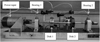 |
Fig. 1 The flexible rotor system. |
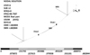 |
Fig. 2 The first order mode shape of the rotor. |
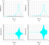 |
Fig. 3 Transient responses of the rotor. (a) Amplitude of disk1. (b) Amplitude of disk2. (c) React force on bearing1. (d) React force on bearing2. |
3 Optimization design
Based on the previous calculation, rotor optimization design is performed in this section. Yet the general, a typical optimization design is set artificially, that is, to reduce the vibration level of the rotor by optimizing the locations of the two disks. The experiment is relatively easy to do because it only needs to move the installation position of two disks without changing other design parameters. The rotor system's dynamic performance may be improved by adjusting the distribution of the rotor's mass and stiffness through changing the locations of the disks. It is difficult to reduce the disks' amplitude and the bearings' react force at the same time. Once the disks' amplitude decreases, it means that the deformation energy of the rotor itself decreases, and the vibration energy of the rotor system is more beard by the support structure, accordingly the bearings' react force will increase; and vice versa. In order to reduce the disks' amplitude and the bearings' react force simultaneously, the total deformation energy of the rotor system should be reduced and well distributed by adjusting the disks' location, which is the desired results of the optimization design.
The amplitude of the disks and the react force on the bearings crossing the first order critical speed are defined as the optimization objectives which are supposed to be minimized through the optimization. Locations of the two disks (represented by Loct_1 and Loct_2 respectively) are set as design variables, which can be left or right moved 10 mm from initial position. Since the normal operating speed of the flexible rotor must be apart sufficiently far from its critical speed, the critical speed should be limited to a certain range. In the present paper, the variation of the critical speed ((represented by Cs) is controlled at the range of ±10%, which is used as the optimization constrains.
A multiobjective design formulation of the rotor may be started as
Minimize F(x) = [Amp_1(x), Amp_2(x), Ref_1(x), Ref_2(x)] where x = (Loct_1, Loct_2)
Subject to 2633 ≤ Cs ≤ 3218 ; 173.5 ≤ Loct_1 ≤ 193.5 ; 322 ≤ Loct_2 ≤ 342
F (x) means the four formulas, i.e., Amp_1 (x) , Amp_2 (x) , Ref_1 (x) , Ref_2 (x). The aim of optimization design is to minimize them using multi-objective optimization.
This optimization design problem can generally reflect the problems that need to be solved in rotor design. The problem is solved using the optimization design method in reference [11]. Figure 4 gives the flow chart of the optimization design process. The optimal location of the two disks is obtained where the four objectives are minimized. Table 1 shows the optimization result.
As can be seen from Table 1, the rotor vibration level decreases when the locations of the two disks are changed. Among the four optimization objectives, the amplitude of disk1 decreases most significantly—decreased by 11%. While the amplitude of disk2 decreased by 2%, almost unchanged.
Next, the uncertainty of unbalance distribution on the rotor is considered. The actual unbalance distribution is definite, but it can be never known for sure. Therefore, assuming that the unbalance distribution is random and uncertain, the uncertain optimization design method is used to optimize the rotor to determine whether considering the uncertainty is meaningful for the rotor design.
It is assumed that the magnitude of unbalance obeys normal distribution and the phase obeys uniform distribution. That is because in the real rotor system magnitude is usually distributed in a certain range, whereas the phase distribution is random. In Section 2, the unbalance on the disk1 and disk2 are determined 25.5 g mm and 17 g mm respectively according to the balance standard. These two values are assumed just the mean values. And it is assumed that the standard deviation is 20% of the mean value. The phase of the unbalance is distributed between 0 and 360 degrees. The rotor is optimized considering the uncertainties shown in Table 2. Notice that the uncertainties of the disks' location are also considered. That is because the actual disks' location is not necessarily the desired value considering the installation error. While, this kind of uncertain is not so great. And it is assumed that the standard deviation is 10% of the mean value.
The design formulation considering uncertainty is started as
Minimize F (μ(x), σ (x))= [μ(Amp_1 (x)), σ (Amp_1(x)), μ(Amp_2(x)), σ(Amp_2(x)), μ (Ref_1(x)), σ (Ref_1 (x)), μ(Ref_2 (x)), σ (Ref_1(x)) ] where x =(μ(Loct_1), σ(Loct_1), μ(Loct_2), σ (Loct_2))
Subject to 2633 ≤ μ (Cs) + 3σ (Cs) ≤ 3218;
173.5 ≤ μ (Loct_1) + 3σ (Loct_1) ≤ 193.5;
The classical 6 Sigma method is used to solve the above optimization problem. In Figure 4, the transient analysis is performed only once in certain variable. While, the transient analysis is performed severe times in uncertain optimization. The response of the optimization objectives under uncertain variables must be evaluated. The results are shown in Table 3. The amplitude response of disk 2 increases after optimization, while the other three objectives are reduced. This is a tradeoff because the uncertain optimization design considers both the reduction of mean value and the reduction of variance.
 |
Fig. 4 flow chart of the optimization design process. |
The rotor optimization design result.
Uncertainties considered in uncertain optimization design.
The rotor optimization design result considering the uncertainties.
4 Experiment
Two sets of optimization results are verified on the rotor test rig shown in Figure 1. In order to simulate the uncertainty of unbalance distribution, screws are added on the two disks in different phases. In real rotor system, the mass of unbalanced phase distribution is random. It may be distributed between 0 and 360 degrees on a disk. Unbalance 22.5 g mm in mass value and [0°, 60°, 120°, 180°, 240°, 300°] in phase range respectively are loaded on Disk1. Thus, 6 kinds of unbalance are added on disk1. Unbalance 18.75 g mm in mass value and [0°, 60°,120°, 180°, 240°, 300°] in phase range respectively are loaded on Disk2. In the same way, 6 kinds of unbalance are added on disk2 consequently. And 36 sets of unbalance due to the two combinations are added to the rotor system artificially.
According to the two sets of optimization results in Tables 1 and 3, the responses of the rotor system are measured respectively with the 36 sets unbalance loaded. The voltage of the bearing's vibration acceleration (represented by Vacc_1 and Vacc_2 respectively) which are directly measured by the acceleration sensors are used to represent the react force on the bearings. The measured data are detailed in Tables 4 and 5. U1, U2, …, U36 represent 36 sets of unbalance artificially added on the disks. Mean and SD represent the mean value and the standard deviation of the 36 sets of measured data.
It can be seen from Table 4 that the amplitude of the rotor and the acceleration response of the bearings are changed when the unbalance distribution of the rotor changes. The response values decrease in some unbalance loading. That is because the unbalance added is just in the contrary phase degree with the original unbalance, which can balance the rotor and reduce the vibration level of the rotor, such as U24, U28 and U30 in Table 4. While other unbalance loading increases the response values, such as U1, U2 and U8. That is because the unbalance added is in the same phase degree with the original unbalance, which can enlarge the rotor unbalance and increase the vibration level of the rotor. The same result applies to Table 5.
Data of each group are very close in Tables 4 and 5. The slight variation may be caused by unbalance distribution or measurement error. Thus, significance test of the measurement results is analyzed using F statistics before comparing the test data. Table 6 gives the significance test result. SS is sum of squares of deviations, DOF is degree of freedom, and MS is mean squares of deviations. BGV is between group variation, WGV is within group variation, and TV is total variation.
The significance level is 0.01. “**” mark are used to indicate the significance, which means the test conditions has a great influence on the differences between groups. Query F distribution table shows that F 0.01 (35,36) = 2.21. F values calculated in Table 6 are greater than F 0.01 (35,36). It can be seen that the difference of measured data between Tables 4 and 5 is caused by the change of unbalance distribution.
Figure 5 illustrates the distribution of mean value and variance of the measured data. The red curve represent the optimization result considering the uncertainties. The smaller the span of the red curve is, the smaller the fluctuation and the more robust the result is. As can be seen from the figure, the mean value of amplitude response of two disks increases slightly, while the mean value of acceleration response on the two bearings decreases considerably. The distribution of four responses is more compact. The four responses are decreased by 14%, 21.5%, 37.2% and 46% respectively in terms of standard deviation, which means that the response of the rotor system is more robust under the excitation of uncertain unbalance.
Measured data of rotor responses without considering the uncertainties under 36 sets of unbalance loaded.
Measured data of rotor responses with considering the uncertainties under 36 sets of unbalance loaded.
Significance test result of the measured data.
 |
Fig. 5 Distribution comparison of the response values with or without considering the uncertainties. (a) Amplitude response of disk1. (b) Amplitude response of disk2. (c) Acceleration response on bearing1. (d) Acceleration response on bearing2. |
5 Conclusions and discussions
In this paper, the optimization design and experiment verification of the rotor system with uncertain unbalance distribution are studied. The traditional optimization design of a two-disk flexible rotor system aiming at vibration control is carried out on the basis of dynamic analysis. After that, the uncertain optimization design considering that the unbalance phase is uniformly distributed and the unbalance magnitude is normally distributed is performed. Experimental comparison of the two optimization results illustrates the advantage of the uncertain optimization design.
With considering or without considering uncertainties, the optimization results can always reduce the objectives in minimum design. When uncertainties are not taken into account, it is limited to determine the optimal result only from the reduction of each optimization objective, because uncertainties may affect the optimization results, especially when the objectives or constraints are sensitive to the design variables.
In fact, uncertain optimization can also improve the reliability of optimization results. But in this paper, the main uncertain factor is unbalance distribution, and the constraint is imposed on the critical speed of the rotor system. The unbalanced distribution only affects the response of the rotor, but does not affect the critical speed. Therefore, the reliability is not evaluated in this paper. If the constraint is sensitive to the unbalance, the reliability of the optimization results will also be improved.
References
- B.G. Choi, B.S. Yang, Optimum shape design of rotor shafts using genetic algorithm, J. Vib. Control 6, 207–222 (2002) [CrossRef] [Google Scholar]
- D.S. Lee, D.H. Choi, Reduced weight design of a flexible rotor with ball bearing stiffness characteristics varying with rotational speed and load, J. Vib. Acoust. 122, 203–208 (2000) [CrossRef] [Google Scholar]
- S.C. Huang, C.A. Lin, Sensitivity analysis and optimization of undamped rotor critical speeds to supports stiffness, J. Vib. Acoust. 124, 296–301 (2002) [CrossRef] [Google Scholar]
- B.S. Yang, S.P. Choi, Y.C. Kim, Vibration reduction optimum design of a steam-turbine rotor-bearing system using a hybrid genetic algorithm, Struct. Multidiscipl. Optim. 30, 43–53 (2005) [CrossRef] [Google Scholar]
- S. Frank, I. Mizuho, S. Jens, Reduction of vibration level in rotordynamics by design optimization, Struct. Multidiscipl. Optim. 34, 139–149 (2007) [CrossRef] [Google Scholar]
- O.P. Alexander, Application of gradient-based optimization methods for a rotor system with static stress, natural frequency, and harmonic response constraints, Struct. Multidiscipl. Optim. 47, 951–962 (2013) [CrossRef] [Google Scholar]
- T.N. Shiau, J.R. Chang, W.B. Wu, Multi-objective optimization of the geared rotor-bearing system for multi-objectives with critical speed constraints, in ASME Turbo Expo 2004: Power for Land, Sea and Air, Vienna, Austria (2004) 14–17 [Google Scholar]
- O.T.C. Matthew, S.K. Patrick, On lmi-based optimization of vibration and stability in rotor system design, in ASME Turbo Expo 2005: Power for Land, Sea and Air, Reno-Tahoe, Nevada, USA (2005) 6–9 [Google Scholar]
- B.G. Choi, B.S. Yang, Multiobjective optimum design of rotor-bearing systems with dynamic constraints using immune-genetic algorithm, J. Eng. Gas Turb. Power 123, 78–81 (2001) [CrossRef] [Google Scholar]
- L.X. Zheng, Sh. X. Jia, J.J. Huang, Numerical and experimental study on the multiobjective optimization of a two-disk flexible rotor system, Int. J. Rotat. Mach. 2017 (2017) [Google Scholar]
- Sh.X. Jia, L.X. Zheng, J.J. Huang, Dynamic characteristics analysis and optimization design of a simulated power turbine rotor based on finite element method, Int. J. Turbo Jet-Engines 37, 31–39 (2020) [CrossRef] [Google Scholar]
- B.G. Liu, Eigenvalue problems of rotor system with uncertain parameters, J. Mech. Sci. Technol. 26, 1–10 (2012) [CrossRef] [Google Scholar]
- H.Y. Zhang, Ch.Q. Bai, Y.J. Mao, Stochastic finite element modeling and response analysis of rotor systems with random properties under random loads, J. Mech. Sci. Technol. 29, 3083–3090 (2015) [CrossRef] [Google Scholar]
- Ch.B. Gan, Y.H. Wang, Sh.X. Yang, Y.L. Cao, Nonparametric modeling and vibration analysis of uncertain Jeffcott rotor with disc offset, Int. J. Mech. Sci. 78, 126–134 (2014) [CrossRef] [Google Scholar]
- J. Hong, J. Wang, M. Chen, Y.H. Ma, Dynamic response analysis of rotor system with uncertain parameters via interval analysis method, in Proceedings of ASME Turbo Expo 2012, Copenhagen, Denmark (2012) [Google Scholar]
- Y.H. Ma, Zh. Liang, M. Chen, J. Hong, Interval analysis of rotor dynamic response with uncertain parameters, J. Vib. Control 332, 3869–3880 (2013) [Google Scholar]
- Y.F. Zuo, J.J. Wang, A method for dynamic analysis of three-dimensional solid element rotors with uncertain parameters, J. Eng. Gas Turb. Power 139, 1–4 (2017) [Google Scholar]
Cite this article as: Shengxi Jia, Longxi Zheng, Qing Mei, Flexible rotor optimization design with considering the uncertainty of unbalance distribution, Int. J. Simul. Multidisci. Des. Optim. 11, 19 (2020)
All Tables
Measured data of rotor responses without considering the uncertainties under 36 sets of unbalance loaded.
Measured data of rotor responses with considering the uncertainties under 36 sets of unbalance loaded.
All Figures
|
Fig. 1 The flexible rotor system. |
| In the text | |
|
Fig. 2 The first order mode shape of the rotor. |
| In the text | |
|
Fig. 3 Transient responses of the rotor. (a) Amplitude of disk1. (b) Amplitude of disk2. (c) React force on bearing1. (d) React force on bearing2. |
| In the text | |
|
Fig. 4 flow chart of the optimization design process. |
| In the text | |
|
Fig. 5 Distribution comparison of the response values with or without considering the uncertainties. (a) Amplitude response of disk1. (b) Amplitude response of disk2. (c) Acceleration response on bearing1. (d) Acceleration response on bearing2. |
| In the text | |
Current usage metrics show cumulative count of Article Views (full-text article views including HTML views, PDF and ePub downloads, according to the available data) and Abstracts Views on Vision4Press platform.
Data correspond to usage on the plateform after 2015. The current usage metrics is available 48-96 hours after online publication and is updated daily on week days.
Initial download of the metrics may take a while.