")
")
| Issue |
Int. J. Simul. Multidisci. Des. Optim.
Volume 13, 2022
|
|
|---|---|---|
| Article Number | 20 | |
| Number of page(s) | 9 | |
| DOI | https://doi.org/10.1051/smdo/2022010 | |
| Published online | 02 August 2022 | |
Research Article
Increasing the waste heat absorption performance in the refrigeration system using electromagnetic effect
Department of Mechanical Engineering, Vel Tech Rangarajan Dr Sagunthala R&D Institute of Science and Technology, Avadi, Chennai, Tamil Nadu, 600 062, India
* e-mail: This email address is being protected from spambots. You need JavaScript enabled to view it.
Received:
12
August
2021
Accepted:
14
June
2022
Abstract
This paper enables a simulation model for analyzing and predicting magnetic field patterns and their magnetic flux density on the pipe. Different types of arrangements of magnets like series, parallel, and Halbach arrays are utilized and their magnetic flux density and magnetic field intensity are compared on the respective pipes. Electromagnetic field simulation software calculates different magnetic fields and circuit parameters. Using this software, accurate results can be obtained such as the perfect arrangement of magnets and so on. For this experimentation, Neodymium-35 type magnets are used which have appropriate and stable magnetic strength as compared to other magnets. Diffusion absorption refrigeration systems can also be used alternatively in domestic refrigeration, thus replacing conventional vapor compression refrigeration systems. Thus, results obtained by using different magnetic arrangements will be highly beneficial to choose the proper magnetic arrangement in diffusion absorption refrigeration system for various cooling applications.
Key words: Ammonia-water bond / electromagnetic simulation / Neodymium-35
© S.M. Jadhav et al., Published by EDP Sciences, 2022
 This is an Open Access article distributed under the terms of the Creative Commons Attribution License (https://creativecommons.org/licenses/by/4.0), which permits unrestricted use, distribution, and reproduction in any medium, provided the original work is properly cited.
1 Introduction
The vapor absorption system for cooling and heating is one of the older techniques which has more energy efficient compared to conventional cooling systems. The vapor absorption system is driven by thermal energy rather than electrical energy which causes the system to save more energy. The mechanical-driven cooling technology consumes more power for operation and its impact on the environment is high. The absorption system was introduced and developed to address the energy crisis and environmental problems associated with conventional cooling systems.
The conventional cooling system is used in the automotive to remove the inner heat to make thermal comfort. This system extracts more energy to power the compressor and the same action is reflected reversely in the mileage. The replacement of the conventional cooling system by a diffusion absorption system that operates on waste energy reduces the power loss as well as produces extra work to run the engine. The excess energy available in the exhaust flue gases is used as the heat input to the diffusion absorption system. Many researchers studied the possibilities to reduce the obstacles associated with diffusion absorption systems and proposed different ideas for the development of an environmentally friendly cooling system. Carlos Amaris et al. [1] studied vapor absorption systems for cooling or heating applications by implementing effective techniques. It was majorly focused on the configuration of an absorber of working fluid at different operating conditions for different absorption models. It should enhance the thermal resistance and heat transfer than that of the falling film, spray, and bubble absorbers. Hui Zhao et al. [2] obtained the salt generation capacity and performance parameter of the absorption refrigeration system using a capacitance deionized regeneration system. The result indicates that the capacitance of deionized water increases the coefficient of performance of the system should increase for the salt regeneration capacitance method. Emil Chibowski et al. [3] reviewed on magnetic field effect on the water during their experimentation. They found that the water gradient was strengthening because of the magnetic field introduced in the water field. The magnetic field was introducing at the inlet of the generator enhances the refrigeration effect, the hydrogen bond, and the water evaporation temperature field. . Pralhad Tipole et al. [4] used a magnet with 3000 gausses to analyze the effect in a vapor compression system with R404A as working fluid. Bhavesh Patel et al. [5] optimized the performance and capital cost by cogeneration system with organic fluid. It was stated that as evaporator temperature increases, the capital cost of the system decreases. S. A. Zonouzi et al. [6] reported the effect of the magnetic field on the nanofluid and found a reasonable enhancement in the heat transfer coefficient. Siyuan Mei et al. [7] introduced a magnetic field on Fe3O4-water nanofluid and studied its thermal effects. Xiao Feng Niu et al. [8] found the absorption enhancement with a magnetic field. The experimental study with different intensities as well as different directions showed a stronger impact on absorption behavior. Siyuan Mei et.al [7] observed the enhancement in the nusselt number due to the magnetic effect. Wang et al. [9] reported the changes in the properties of working fluid with a magnetic field. The magnetization changed the specific heat and boiling point of the working fluid. Dongdong Feng et al. [10] improved mass transfer in CO2 absorption with the help of high-intensity magnets. Agata Czernuszewicza et.al [11] studied the magnetization effect to improve the system performance. This paper experimentally studied to use of the waste energy from the exhaust of stationary engines to produce a refrigerating effect. The results obtained can also be improved by using various magnetic arrangements such as a circular array, linear Halbach array in series, and parallel arrangements. Optimization of different magnetic arrangements is done using Electromagnetic stimulation (EMS) software. Currently, the diffusion absorption refrigeration system is not using heat as an input. In abroad countries, the DAR systems are available in the market but working on high-grade energy i.e. electricity. So, experimentation is done on reutilizing the waste heat from the exhaust of internal combustion engines to obtain Refrigerating Effect along with magnetic field utilization.
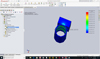 |
Fig. 1 Electromagnetic field simulation (EMS) software. |
2 Electromagnetic simulation (EMS) software
Electromagnetic simulation (EMS) software provides a platform to analyze the electrical and magnetic effects with more accuracy. This software is integrated with design modules like Solid works and Autodesk which help us to do simulations without any modifications. This Multiphysics software enables us to couple magnetic and thermal analyses without any additional inputs. The magnetic flux density and intensity were the main output of each study. This software is equipped with many technical advantages including magnetic saturation and minimizing the cogging torque. The application of this software extended to the study of the charging behavior of electrical vehicle batteries, micro electro mechanical system study, and biomedical applications. Figure 1 shows the working view of the Electromagnetic simulation (EMS) software.
3 System description
The objectives and Scope of this experimentation are as follows:
To achieve refrigerating effect by vapor absorption refrigeration system rather than using traditional vapor compression refrigeration system.
To recover waste energy from the exhaust and run an air conditioning system.
To enhance the various parameter of the vapor absorption refrigeration system using different arrangements of magnetic field i.e. circular, series, and parallel Halbach array.
 |
Fig. 2 DAR system and location of magnets on set up. |
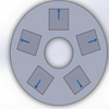 |
Fig. 3 Circular array. |
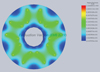 |
Fig. 4 Magnetic flux density circular array. |
As shown in Figure 2, the experimental setup of the vapor absorption system has the following components:
Absorber
Generator
Air cooled condenser
Temperature indicators
Energy meter
4 Results and discussions
While selecting the different arrays for comparison, several trials with Halbach circular array, with all magnets facing towards the pipe, few magnets arranged clockwise and few in an anticlockwise direction, linear Halbach array in series and parallel arrays were taken. Among these, all trials, circular array, linear Halbach array in series, and parallel arrangement are taken for comparison. The magnetic flux density and magnetic field intensity are compared. The results of various arrangements are discussed below.
4.1 Circular array
Figure 3 shows the arrangement of magnets with their directions i.e. coercivity in EMS software and the magnetic flux density in Tesla in the right picture. All magnets are arranged to keep the N pole facing away and the S pole towards the pipe. As shown in Figure 4, the magnetic flux density is evenly distributed around the center along with symmetry in flux lines but the value is very low. This value of magnetic flux density has occurred in the range of 0.1 to 0.6 Tesla which is very less as compared to series and parallel Halbach arrays.
As shown in Figure 5, the value of Magnetic Field Intensity is moderate but less as compared to series and parallel Halbach arrays. The value of Magnetic Field Intensity varies in the range of 3.609e+5 to 6.495e+6. These values of magnet magnetic flux density and Magnetic Field Intensity in the circular array are less because the mixture of NH3-H2O which is passing through the pipe is having very less access to the magnetic field. Hence, there is less effect of magnetic field on mixture properties. Because of this reason, the circular array cannot be utilized for experimentation. Magnetic Field Intensity is fully directed at the core of the pipe which can be observed by the direction of magnetic field lines. But the value of magnetic field intensity i.e. average of all the lines is not sufficient enough to break the NH3-H2O bond.
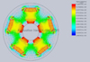 |
Fig. 5 Magnetic field intensity. |
| Results for Circular Array | |
|---|---|
| Magnetic Flux Density (Tesla) | 0.1 − 0.6 |
| Magnetic Field Intensity (Amp/m) | 3.609e+5–6.495e+5 |
4.2 Linear Halbach array
Figure 6 depicts the amount of Magnetic Flux Density (Tesla) i.e. no. of Magnetic flux lines per m2. As observed in Figure 6, there is more magnetic flux intensity at the junction of the two magnets. The arrangement of the linear Halbach array is done in such a manner that the N pole rotates in an anticlockwise direction and all five magnets are fixed together. The value of magnetic flux density can be calculated accurately by taking an average of values shown in the value bar.
Figure 7 shows the direction of magnetic field lines along with their magnetic field intensity in Amp/m. For Linear Halbach Array the magnetic field intensity is quite high only on one side and weak on another side of the magnetic array. Hence, a single array will not be effective for lowering the boiling point of the NH3-H2O mixture which is flowing through the pipe. On the other side, the magnetic field effect can be enhanced by arranging two sets of Halbach arrays either in series or parallel. Hence, the linear Halbach array gives a scope of utilizing the two magnetic arrangements i.e. series and parallel arrays.
| Results for Linear Halbach Array | |
|---|---|
| Magnetic Flux Density (Tesla) | 0.233 − 0.436 |
| Magnetic Field Intensity (Amp/m) | 4.67e+5– 9.5e+5 |
4.3 Linear Halbach array in a series arrangement
As shown in Figure 8, both sets of linear Halbach arrays are arranged linearly along the circumference of the pipe i.e. the magnets are tangent to the outer surface of the pipe. Both sets of linear Halbach arrays are placed on the pipe in such a manner that their strong side is facing the pipe and the weak side away from the pipe. As shown in Figure 9, the direction of magnetic flux lines in the simulation depicts that the number of lines crossing the inner surface of the pipe is moderate and the magnetic flux lines at the circumference are densely distributed along the outer side of the pipe. But, the magnetic effect can be enhanced by arranging two sets of linear Halbach array in series. The value of Magnetic Flux Density is in the range of 1.2 to 2.95 Tesla. This value is more than that of the circular array and less than that of the linear Halbach array in a parallel arrangement. The value of magnetic field intensity varies from 6.46e+5 to 1.01e+6 Amp/m.
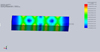 |
Fig. 6 Magnetic flux density for linear Halbach array. |
 |
Fig. 7 Magnetic field intensity for linear Halbach array. |
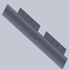 |
Fig. 8 Series Halbach array. |
| Results for series Halbach Array | |
|---|---|
| Magnetic Flux Density (Tesla) | 0.9–1.7 |
| Magnetic Field Intensity (Amp/m) | 6.46e+5 − 1.01e+6 |
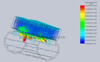 |
Fig. 9 Magnetic flux density for series Halbach array. |
 |
Fig. 10 Parallel Halbach array. |
4.4 Linear Halbach array in a parallel arrangement
Figure 10 shows the linear Halbach array in a parallel arrangement. For Halbach Arrays, the direction of the magnets is rotated by 90° in an anticlockwise direction. The value of magnetic flux density varies in the range of 1.2 to 2.95 Tesla and magnetic field intensity ranges from 9.57e+5 to 1.34e+6 Amp/m. In comparison with circular and linear Halbach array in a series arrangement, a linear Halbach array in parallel arrangement gives better results in magnetic flux density and magnetic field intensity. The reason behind these better results is the arrangements of Halbach arrays. Both sets of magnetic arrays are mounted facing each other which forms a considerably strong magnetic field. The mixture of NH3-H2O flows through this strong magnetic field. Hence, there are considerable changes in the physical properties NH3-H2O mixture. The bond between the NH3 and H2O gets weakened and the ultimate effect is the reduction in the boiling point of the NH3-H2O mixture. Hence, a linear Halbach array in a parallel arrangement is recommended for performance enhancement.
The magnetic field intensity for linear Halbach array in the parallel arrangement was found to be uniform and strong enough compared to other arrangements i.e. circular and linear Halbach array in a series arrangement. The magnetic field intensity is concentrated at the pipe diameter which is very useful for breaking the NH3-H2O bond.
 |
Fig. 11 Magnetic flux density for parallel Halbach array. |
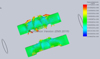 |
Fig. 12 Magnetic field intensity for parallel Halbach array. |
| Results for Parallel Halbach Array | |
|---|---|
| Magnetic Flux Density (Tesla) | 1.2–2.95 |
| Magnetic Field Intensity (Amp/m) | 9.57e+5 − 1.34e+6 |
5 Validation
The extensive experiment has been performed to understand how linear array, linear Halbach array with series, and parallel arrangements influence the diffusion absorption refrigeration system. So, experimentation was conducted using a natural, linear Halbach array with series and parallel arrangements with the help of the experimental set up shown in Figure 2. Comparing various magnetic arrangements, linear Halbach array with parallel arrangement gave a remarkable reduction in refrigeration cabinet temperature. As shown in Figure 13, refrigerator cabinet temperature is reduced up to 9 °C within 22 min without using any magnetic field arrangement. Refrigerator cabinet temperature is reduced up to 10 °C within 18 min using linear Halbach array with the series arrangement. Whereas, refrigerator cabinet temperature is reduced up to 6 °C within 12 minutes using a linear Halbach array with the parallel arrangement. These results show that linear Halbach array is the most suitable magnetic field arrangement to reduce refrigerator cabinet temperature within a short period.
To understand whether the above results obtained from the experimentation can be validated, EMS software was utilized. Using EMS software analysis, it was found that a circular array is not at all suitable for magnetic field enhancement. While conducting simulation with EMS software, circular array, linear Halbach array with series, and parallel arrangements were considered. Magnetic flux density and magnetic field intensity were compared for various magnetic field arrangements. It was found that magnetic flux density and magnetic field intensity for linear Halbach array with the parallel arrangement are highest and least for the circular array. Figure 14 shows the comparison between circular array, linear array, linear Halbach array with series and parallel arrangements. Linear Halbach array with parallel arrangement showed the highest magnetic flux density i.e. 2.1 Tesla. Hence, it validates that a linear Halbach array with a parallel arrangement is suitable for enhancement of magnetic flux density which weakens the hydrogen bond and reduces the boiling point up to 135 °C in a linear Halbach array with the parallel arrangement.
Figure 15 shows the comparison of magnetic field intensity for various magnetic arrangements. Linear halbach array with a parallel arrangement is the most suitable arrangement as it enhances the magnetic field intensity. The highest magnetic field intensity is 1.15E+06 Amp/m for a linear Halbach array with a parallel arrangement which helps to weaken the hydrogen bond and reduces the boiling point up to 135 °C.
The boiling point at which ammonia is separated from the water is 170 °C without any magnetic field. This boiling point can be reduced by applying various magnetic field arrangements such as a circular array, linear array, linear Halbach array with series and parallel arrangements. The linear Halbach array with parallel arrangement gave remarkable enhancement in magnetic flux density and magnetic field intensity as shown in Figures 14 and 15. Enhancement in magnetic flux density and magnetic field intensity helps to reduce the boiling point of water by weakening the hydrogen bond. Figure 16 shows that the boiling point without any magnetic field is 170 °C. The boiling point for linear Halbach array with series and parallel is 150 °C and 135 °C respectively. Hence, it is validated that a linear Halbach array with a parallel arrangement is the most suitable magnetic field arrangement for the performance enhancement of vapor absorption refrigeration system.
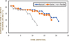 |
Fig. 13 Refrigerator cabinet temperature vs time. |
 |
Fig. 14 Magnetic flux density for various magnetic arrangements. |
 |
Fig. 15 Magnetic field intensity for various magnetic arrangements. |
 |
Fig. 16 Boiling point for different magnetic arrangements. |
6 Conclusion
In a comparison of circular, linear Halbach array in series and parallel arrangement, linear Halbach array with parallel arrangement gave a remarkable enhancement in magnetic flux density and magnetic field intensity. Circular and simple linear arrays did not give considerable results as those arrangements cannot cover the maximum surface of the pipe with a magnetic field. Hence, circular and simple linear arrays are not recommended for the performance enhancement of diffusion absorption refrigeration systems. Implementation of magnets in different arrangements i.e. series and parallel proved that there is a reduction in temperature for separation of ammonia from water in the generator which would lead to a decrease in input heat by exhaust gas and an increase in performance of apparatus. In comparison to series and parallel arrangements, linear Halbach array in parallel arrangement gave remarkable enhancement in magnetic flux density and magnetic field intensity. Hence, in Recreational vehicles implantation of a linear Halbach array with a parallel arrangement will lead to improvements in the performance of the refrigeration and air conditioning system.
References
- C, Amaris, M. Valles, M. Bourouis, Vapour absorption enhancement using passive techniques for absorption cooling/heating technologies, Appl. Energy 231, 826–853(2018) [CrossRef] [Google Scholar]
- Z. Hui, X. Zhang, X. Li, B. Ding, F. Cheng, Research on actual performance and energy recovery characteristic of capacitive deionization regeneration method for absorption air-conditioning system, Energy Convers. Manag. 171, 1549–1559 (2018) [CrossRef] [Google Scholar]
- E. Chibowski, A. Szczesny, Magnetic water treatment − a review of the latest approaches, Chemosphere 203, 54–67 (2018) [CrossRef] [PubMed] [Google Scholar]
- T. Pralhad, A. Karthikeyan, V. Bhojwani, S. Deshmukh, B. Tipole, K. Shinde, A. Sundare, D. Shendage, Performance analysis of vapor compression water chiller with magnetic flux at the condenser exit, Energy Build. 158, 282–289 (2018) [CrossRef] [Google Scholar]
- B. Patel, N.B. Desai, S.S. Kachhwaha, Optimization of waste heat based organic Rankine cycle powered cascaded vapor compression-absorption refrigeration system, Energy Convers. Manag. 154, 576–590 (2017) [CrossRef] [Google Scholar]
- S.A. Zonouzi, R. Khodabandeh, H. Safarzadeh, H. Aminfar, Y. Trushkina, M. Mohammad Pourfard, M. Ghanbarpour, G.S. Alvarez, Experimental investigation of the flow and heat transfer of magnetic nanofluid in a vertical tube in the presence of magnetic quadrupole field, Exp. Therm. Fluid Sci. 91, 155–165 (2018) [CrossRef] [Google Scholar]
- S. Mei, C. Qi, T. Luo, X. Zhai, Y. Yan, Effects of magnetic field on thermo-hydraulic performance of Fe3O4-water nanofluids in a corrugated tube, Int. J. Heat Mass Transfer 128, 24–45 (2019) [CrossRef] [Google Scholar]
- X. Feng Niu, K. Du, F. Xiao, Experimental study on ammonia-water falling film absorption in external magnetic fields, School of Energy and Environment, Southeast University, SiPaiLou, Nanjing, Jiangsu, 210096 [Google Scholar]
- Y. Wang, H. Wei, Z. Li, Effect of magnetic field on the physical properties of water, Res. Phys. 8, 262–267 (2018) [Google Scholar]
- D. Feng, J. Gao, Y. Zhang, H. Li, Q. Du, S. Wu, Mass transfer in ammonia-based CO2 absorption in bubbling reactor under static magnetic field, S1385-8947(18)30076-7 (2018) [Google Scholar]
- A. Czernuszewicza, J. Kaletab, D. Lewandowskib, multicaloric effect: toward a breakthrough in cooling technology, Energy Convers. Manag. 178, 335–343 (2018) [CrossRef] [Google Scholar]
Cite this article as: Sahadev Murlidhar Jadhav, Arulprakasajothi Mahalingam, Vikas Vasantrao Ugle, Logesh Kamaraj, Increasing the waste heat absorption performance in the refrigeration system using electromagnetic effect, Int. J. Simul. Multidisci. Des. Optim. 13, 20 (2022)
All Figures
|
Fig. 1 Electromagnetic field simulation (EMS) software. |
| In the text | |
|
Fig. 2 DAR system and location of magnets on set up. |
| In the text | |
|
Fig. 3 Circular array. |
| In the text | |
|
Fig. 4 Magnetic flux density circular array. |
| In the text | |
|
Fig. 5 Magnetic field intensity. |
| In the text | |
|
Fig. 6 Magnetic flux density for linear Halbach array. |
| In the text | |
|
Fig. 7 Magnetic field intensity for linear Halbach array. |
| In the text | |
|
Fig. 8 Series Halbach array. |
| In the text | |
|
Fig. 9 Magnetic flux density for series Halbach array. |
| In the text | |
|
Fig. 10 Parallel Halbach array. |
| In the text | |
|
Fig. 11 Magnetic flux density for parallel Halbach array. |
| In the text | |
|
Fig. 12 Magnetic field intensity for parallel Halbach array. |
| In the text | |
|
Fig. 13 Refrigerator cabinet temperature vs time. |
| In the text | |
|
Fig. 14 Magnetic flux density for various magnetic arrangements. |
| In the text | |
|
Fig. 15 Magnetic field intensity for various magnetic arrangements. |
| In the text | |
|
Fig. 16 Boiling point for different magnetic arrangements. |
| In the text | |
Current usage metrics show cumulative count of Article Views (full-text article views including HTML views, PDF and ePub downloads, according to the available data) and Abstracts Views on Vision4Press platform.
Data correspond to usage on the plateform after 2015. The current usage metrics is available 48-96 hours after online publication and is updated daily on week days.
Initial download of the metrics may take a while.