")
")
| Issue |
Int. J. Simul. Multidisci. Des. Optim.
Volume 10, 2019
Special Issue - Uncertainty-Based Design Optimization
|
|
|---|---|---|
| Article Number | A5 | |
| Number of page(s) | 11 | |
| DOI | https://doi.org/10.1051/smdo/2019006 | |
| Published online | 15 March 2019 | |
Research Article
Investigation of machinability characteristics on C45 steel with cryogenically treated M2 HSS tool using statistical technique
1
School Mechanical Engineering, REVA University, Bangalore, India
2
School of Electronics and Communication Engineering, REVA University, Bangalore, India
3
Department of Mechanical Engineering, MITE, Moodbidri, Mangalore, India
* email: This email address is being protected from spambots. You need JavaScript enabled to view it.
Received:
7
August
2018
Accepted:
14
February
2019
Abstract
The machining industries always eye on increasing hardness and reducing the friction at the cutting tool–workpiece interface to reduce flank wear, thereby enhancing the tool life. The present study investigates the effect of deep cryogenic treatment (DCT) on the behavior of M2 HSS tool in turning of C45 medium carbon steel. The tool is double tempered and is tested for hardness and flank wear. The power consumption is also analyzed in the process with a focus on green machining. While Taguchi's L 27 orthogonal array (OA) is used to study the main interaction effect of all machining parameters, analysis of variance (ANOVA) and signal to noise (S/N) ratio are used for analysis of experimental outcomes. The study reveals that DCT has enhanced the hardness of HSS tool by 14.9%, while speed and feed were the dominating factors on the flank wear. Microstructure morphology using SEM is also discussed.
Key words: M2 HSS tool / Deep cryogenic treatment / Hardness / Flank wear / Machining
© S. Kumar et al., published by EDP Sciences, 2019
 This is an Open Access article distributed under the terms of the Creative Commons Attribution License (http://creativecommons.org/licenses/by/4.0), which permits unrestricted use, distribution, and reproduction in any medium, provided the original work is properly cited.
1 Introduction
In manufacturing process, the production costs increase due to constant tool wears. The tool being cut is also hard and poses huge friction to the cutting tool. Many attempts to reduce friction have provided poor results. The precision and efficiency are inversely proportional to the duration of tool usage as wear increases with time. An ideal cutting tool is expected to exhibit hardness by withstanding the frictional force, high temperature, and residual stress generated at interface during the machining. A harder and wear resistant tool is preferred in high-speed cutting due to its high ergonomics.
To enhance the tool life, cryogenic treatment (CT) has emerged as a promising candidate, where the cutting tool is exposed/treated under extreme temperature conditions. Deep cryogenic treatment (DCT) is a new and efficient method of CT, where the tool is treated from ambient temperature to −193 °C and back [1]. To further enhance the tool condition tempering can be done, where the tool is heated to 150 °C and cooled suddenly to room temperature. Tempering is done after DCT and can be of multiple cycles. Molybdenum has successfully replaced tungsten during World War [2] and is still preferred in small scale industry due to its affordability and few superior qualities as compared to its counterpart [3]. The molybdenum-based HSS tool finds its application as taps, drills, milling cutters, broaches, and bits [4]. Heat treat of HSS tool will greatly increase the range of properties such as wear resistance and hardness. Strong cutting tool suppresses friction, thereby controlling temperature and demanding less power to overcome the stress. Many efforts have been put in understanding the impact of CT during machining. But very few works focus on impact of DCT on tool life of M2 HSS tool used for dry machining of C45 [5]. The investigations on relevance of cutting parameters on hardness and flank wear lack clarity. The study on power consumption during turning is missing in literature.
This work attempts to show the effect of DCT on hardness, flank wear, and power consumption. Here, the current literature is reviewed; research gaps are identified and addressed. The performance evaluation of DCT tool is compared with untreated tool for hardness and flank wear. The cutting parameters are optimized using Taguchi's technique and experimental results are analyzed using analysis of variance (ANOVA) [and signal to noise ratio (SNR)] methods. The remainder of the paper is organized as below: Section 2 provides a comprehensive background of CT, while Section 3 reviews the current efforts made in this regard. Section 3.1 explains the design of experiment (DOE); Section 4 presents the results. Finally, paper concludes with future work and outlook in Section 5.
2 Background
A typical setup of machining is shown in Figure 1. The fixed cutting tool mounted on tool post will cut the workpiece which will be rotating at a fixed rate. Dynamometer present measures the cutting force immediately below the interface. The dynamometer employs four sensors for the conversion of strain deflection to force. These sensor outputs are fed to data acquisition (DAQ) system where the input undergoes signal conditioning. Initially, it is amplified, filtered, and then converted from analog to digital domain. This digital output of DAQ is fed to the computer terminal where data is stored and analyzed for further process.
In the manufacturing industry, wear resistance, machining cost, and tool life play a vital role. At the tool–workpiece interface, excess heat and wear are produced leading to inferior quality product and manufacturing overhead. A sustainable manufacturing process must reduce the heat generated and should use hardened, a wear-resistant cutting tool with extended tool life. These situations have led to investigations in various treatments of metals and materials to have morphological changes at the structural level. CT stands as a promising and prospective candidate for treating cutting tools. (1)where “v” represents cutting velocity in m/min, “T” is tool life, “n” is a constant based on tool material, and “C” is a constant based on tool and work.
A typical CT setup is shown in Figure 2. A microcontroller-based control system is designed to control the flow of liquid nitrogen (LN2) into the cooling chamber. The cutting tools are placed in the chamber where the atomized nozzles will spray the LN2 for direct cooling.
Treating metals and materials under extreme temperature conditions to have morphological changes is an ancient art [6]. In pursuit of enhancing the stability of a workpiece–tool, many efforts have been carried out by treating them to extremely high temperatures and/or shallow temperatures. The process of transforming unstable phases into a stable at room temperature by operating the metal at a cold temperature of −120 °C and beyond is termed as CT [7]. It refers to deep and slow cooling of the metal in a controlled bath of LN2. This CT enhances durability, improves wear resistance, and decreases residual stresses while increasing the toughness and dimensional stability. The CT has a profound effect on resistance to impact by creating more uniform grain structure [8]. It finds its applications in aerospace and defense, medical and automotive, sports and music, and forming and cutting tools [9]. Cutting tools can be cryogenically treated in two methods: DCT refers to treating heated cutting tool to the cold temperature of up to −196 °C, whereas shallow cryogenic treatment (SCT) refers to a different cooling temperature of about −110 °C [10].
Recently, a cryogenic machining method has surfaced in the field of CT research. Instead of cooling tools separately, a jet of LN2 is sprayed at the interface of the cutting tool [11]. Though it is useful in machining operation (especially for rough machining), still it is in limited to research labs and the widespread acceptance of this method is hindered due to the health hazards caused by direct exposure to LN2. While treating refers to a process of applying distinct time/temperature profile to modify the performance of materials, tempering relates to a method of heating a tool (instead of cooling) and cools it in still air. It will increase the toughness of iron-based alloys but used to reduce the excess hardness achieved during DCT [12]. One can have multiple cycles of tempering based on the required hardness [13]. The tempering temperature is selected based on the alloy composition and the requirements of the finished product [14].
Figure 3 shows the CT cycle, where the first stage called cooling is done by reducing room temperature to −196 °C at the rate of 20c per minute. The second stage called soaking (or holding period) is carried for few hours (<35 h) followed by heating to achieve the ambient temperature. Further, tempering can be done for the removal of excess hardness [15].
Though CT and especially DCT will remarkably enhance the properties of the tool and increase machinability, very few works have been carried out [16]. Molinari et al. made one of the first attempts on the study of the impact of DCT on hardness in 2001, where they achieved 50% cost reduction due to increased hardness and reduced tool consumption [14]. In 2003, Huang et al. postulated that the improvement in wear resistance of cryo-treated tool could be owed to rise in the carbide density and volume fraction of machine tool [17]. This implies that there is an impact of cryo-treatment on the microstructure of the tool material. Another work later supported the theory by Flavio et al. in 2006, where their study reveals that the percentage of austenite drops to 0% after treatment from 25% initially (before CT). The work by Firozdar and team gave a massive boost to incorporating tempering in DCT. According to the results, they were successful in achieving 77% change and 126% change in hardness due to CT and CTT (CT followed by tempering). Another experiment by Pellizzari et al. in 2008 achieved a reduction of 32% and 49% of wear rate due to advancement to a double and triple tempering (respectively) of the treated tool [18].
We can conclude that the transformation of retained austenite to martensite is the key for upgraded hardness. As per the ISO-3685-1993 standards [19], maximum flank wear of M2 HSS tool can be 0.6 mm. In 2011, Swarandeep and team exhibited tool life improvement by 21.81% and 51.11% due to SCT and DCT [20]. As enhanced hardness was owed to increase in carbide density, Dhokey et al. in 2012 [21] reported that the tertiary carbide produced during CT at the 4 h soaking time is responsible for increased wear resistance. Reddy et al. in 2015 achieved a marginal change in hardness when CT resulted in the formation of n-phase carbides instead of removal of retained austenite [22]. In 2016, Sharma and Crew did a comparative study on DCT processed high steel for secondary hardness [16]. The investigation revealed that low-temperature treatment formed higher carbide concentration and increased hardness.
With the existing survey, we can summarize that CT has permanent and irreversible effect at microstructure level. CT increases hardness and this improvement is due to increased carbide density. CT has two types: SCT and DCT, where DCT is more effective in improving the hardness of M2 HSS tool. Tempering (multiple times) will also increase the toughness and assist in removing excess hardness.
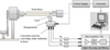 |
Fig. 1 A symbolic representation of experimental setup depicting workpiece being machined by cutting tool. Data acquisition is done after dynamometer senses force and fed to local server/host for analysis. |
 |
Fig. 2 A typical representation of cryogenic treatment process. |
 |
Fig. 3 Deep cryogenic treatment cycle with double tempering. |
3 Experimental setup
Here in this work, we have considered AISI M2 HSS tool for dry machining, turning operation of hot-rolled C45 steel. Treated and untreated cutting tools carry orthogonal cutting as shown in Figure 4. The treated material has undergone DCT followed by double tempering. The turning operation was performed using panther 1350/1 center lathe machine equipped with maximum spindle rotation of 1250 rpm and 7.5 kW drive motor. The cutting operation was conducted at three different cutting speeds (384, 572, and 625 rpm), three different feed (0.046, 0.062, and 0.087 mm/rev), and three different depth of cuts (0.2, 0.4, and 0.6 mm). The chemical composition of AISI M2 HSS tool used for this work is shown in Table 1. The angles of cut described in Table 2 vary according to various factors. Miranda tool booklet was taken as reference for selecting them.
An electron discharge spectrography (EDS) through X-rays was conducted on the top surface of both treated and untreated tool for chemical composition. The images are evident for few morphological changes that have occurred due to CT. The EDS image of the treated tool is shown in Figure 5.
Hardness was measured on the Rc scale using Rockwell hardness tester, and sandpaper was used to prepare a flat surface of the tool. To settle the specimen a minor load of 10 kg was applied, later replaced by 150 kg of the major load for about 15 s. A dial gauge was used to record the resistance to indentation automatically. An average of total six readings for both samples (treated and untreated) was documented as shown in Table 3.
CT plays a vital role in developing steel tribological properties [23]. There have been few efforts in optimizing the CT parameters. Based on the analysis of various heat treatment parameters, DCT conditions are decided. The overwhelming popularity of steel and the success rate of DCT enforce us to explore the optimization techniques [24]. Traditionally, the optimization is done on trial-and-error basis depending on the manufacturer's data sheet and design engineer's specification [25]. Since these details pertain to general steel, it might not be suitable for treated one; also, it is cumbersome to optimize when the number of process parameters rises.
In the given scenario, Taguchi DOE stands out as the best candidate for critical parameter optimization of a given process [26]. It is a statistical method, where optimization is achieved by decreasing the variation in time. The independent simultaneous evaluation of two or more variables is possible by Taguchi's orthogonal series. The difference between experimental value and the desired value is converted into a loss function, which is used in the calculation of standard deviation. This loss function turns data into signal to noise (S/N) ratio. Thus, largest SNR represents the best performance [27]. There are three categories of S/N ratio performance: nominal is best (such as loss, as nominal as possible), smaller is the better (such as wear, as lower as possible), and higher is the better (such as material removal rate, as large as possible). In the current study, S/N ratio is calculated with an approach of smaller is the better [28].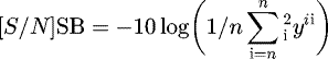 (2)where “yi
” is the observed data at ith experiment and “n” is number of experiments.
(2)where “yi
” is the observed data at ith experiment and “n” is number of experiments.
 |
Fig. 4 M2 HSS tool before and after profile grinding. |
Chemical composition of AISI M2 HSS tool.
AISI M2 HSS tool signature.
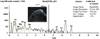 |
Fig. 5 Electronic dispersive spectrography of the deep cryo-treated tool. |
Experimental data obtained during hardness test.
3.1 Design of experiment
In the turning process, the impact of DCT and machining parameters on the flank wear and power consumption were investigated using Taguchi optimization technique. The Taguchi L 27 313 standard 3-level orthogonal array possessing 26 degree of freedom (DOF) was chosen in this study [29]. Thus, each picked parameter was probed at three levels. Table 4 shows the quality characteristics of flank wear and power consumption for untreated and cryo-treated, respectively.
ANOVA aids us in investigating the significance of the impact of experimental design parameters. ANOVA results for flank wear, “P > F” is less than 0.05, and the control factors and their interactions are significant. The effect of cutting speed, feed, and depth of cut on flank wear and power consumption has been determined by applying ANOVA with 95% reliability. In the current study, the most effective parameter on flank wear is feed rate with percentage contribution of 35.30% for untreated and depth of cut is 46.73% contribution for treated, respectively. Similarly, depth of cut was the dominating factor in power consumption with a contribution of 55.67% for untreated and cutting speed is 39.51% contribution for treated, respectively. Similar investigations of flank wear are tabulated in Tables 5 (UT) and 6 (CT), and power consumption tabulated in Tables 7 (UT) and 8 (CT) was carried out. A response table for S/N ratio in Table 9, the main effect's plots for S/N ratios of every individual response, was drawn in the most influencing machining parameter and the optimal parametric setting, respectively. In S/N ratio, signal is the desired value while noise is the undesired one. Thus, the most significant (highest) S/N ratio represents optimized value. The average S/N ratio of flank wear (treated and untreated) and power consumption (treated and untreated) values from experimental studies were calculated as 7.8, 12.3, −17.8, and −15.0, respectively. Here, cutting speed seems to be the most dominating variable while depth of cut being the least. The optimal condition of process variables was obtained as: cutting speed at 384 rpm, the feed at 0.046 mm/rev, and depth of cut at 0.4 mm for untreated, while cutting speed at 384 rpm, the feed at 0.046 mm/rev, and depth of cut at 0.6 mm for treated cutting tool.
Results of quality characteristics of flank wear and power consumption for untreated and cryo-treated, respectively.
Analysis of variance results for flank wear (UT).
Analysis of variance results for flank wear (CT).
Analysis of variance results for power consumption (UT).
Analysis of variance results for power consumption (CT).
Results of S/N ratio for flank wear and power consumption.
4 Results and discussion
Table 3 shows the HRc value of M2 HSS tool for both untreated and treated assessed by Rockwell hardness tester. Hardness is not an elementary property of a material and must be defined by tests. There is no standard table for hardness and must be measured in a specific manner through a specified indenter shape [30]. The changes in hardness of cutting tool subjected to DCT are shown in Figure 6. The mean values pertaining to hardness were 53.66 and 61.66 for untreated and treated tool, respectively, depicting an improvement of about 14.9% in hardness. The variations of flank wear in both treated and untreated M2 HSS tools at a feed of 0.046, 0.062, and 0.087 mm/rev with cutting speeds of 384, 572, and 625 rpm for a depth of cut of 0.2, 0.4, and 0.6 mm, respectively, are shown in Table 4. During the experiment, at all combination of cutting conditions, the deep treated tool exhibited performance better than the untreated concerning flank wear and power consumption.
The first nine experiments were conducted, keeping the depth of cut constant at 0.2 mm. At a speed of 384 rpm and feed of 0.046, 0.062, and 0.087 mm/rev, improvement of 100%, 125%, and 50% in flank wear were observed, respectively. Similarly, at a speed of 572 rpm and feed of 0.046, 0.062, and 0.087 mm/rev, improvement of 100%, 164.7%, and 183.3% in flank wear were observed, respectively. A reduced improvement of 79.2%, 113.3%, and 87.5% was noted when all three feeds were applied at the speed of 625 rpm, respectively.
The second set of experiments was carried out by changing the depth rate to 0.4 mm. The highest improvement was noted to be 95.5% at a lower speed, while only 55.59% were reported at more considerable speed. A similar change of percentage in flank wear was observed (in the third set) with a maximum improvement of about 39.8% at a lower rate and 25.8% at a higher speed at a depth of cut of 0.6 mm.
To illustrate the impact of DCT on the flank wear mechanisms, SEM pictures of both untreated and cryo-treated (deep) worn are depicted in Figure 7. SEM images were used to analyze the microstructures of both treated and untreated samples. The samples were prepared by following a scientific process of polishing using silicon carbide emery papers (of 600, 800, and 1000 grades), super finishing by diamond paste on a velvet cloth, and finally washing them using acetone followed by drying in still air. Microstructure samples were revealed at a magnification of 100 μm and 500 μm.
Due to abrasive wear mechanism, flank wear was evident on both treated and untreated cutting tool. The oxidation and adhesive wear mechanisms also resulted in notch wear in both the tools. Similarly, the manifestation of built-up-edge (BUE) on the cutting edge of tools was visible. The abrasive and diffusion wear mechanisms had resulted in craters on the rake faces on both the cutting tools. From the SEM images, we can infer that treated tool exhibits less flank wear and crater wear in contrast with untreated one. We can also conclude that as speed increases the possibility of flank wear increases correspondingly.
These are ȵ-carbides formed during the tempering cycles which play a vital role in the enhancement of hardness and provide more excellent wear resistance. Martensite in the tempered condition and precipitated carbide particles while retaining some amount of austenite are the reason for the improvement in responses. The decreased temperature in CT leads to distortions in the lattice structure and thermodynamic instability of martensite. Hence, the nearby imperfections of the lattice are occupied by alloying elements and carbon resulting in the formation of fine carbides on tempering. This increased concentration of fine carbides impacts the wear resistance and hardness positively.
In the current investigation, Taguchi method was employed for the optimization of each output response. For every individual response was shown to obtain most influencing machining parameter and the optimal parametric setting, respectively, as demonstrated in Figure 8 (a) V B untreated, (b) V B treated, (c) P c untreated, and (d) P c treated. It can be observed from Table 5 that depth of cut is the most affecting variable on flank wear V B, while the cutting speed being the least in treated tool. In other hand, cutting speed is most affecting variable on power consumption P c, while depth of cut is least in treated tool. The optimal combination of process variables is obtained from the main effect's plots. Thus, the optimal combination of process variables is observed as follows: depth of cut at 0.2 mm, cutting speed at 62.8 m/min, and the feed at 0.087 mm/rev (for V B treated cutting tool), and depth of cut 0.2 mm, cutting speed at 38.6 m/min, and feed at 0.046 mm/rev, respectively (for P c treated tool).
A comparative study of the results obtained using both the cutting tools was carried out to show the better ability and adaptableness of cryo-treated cutting tools in various manufacturing applications. From the experiments, flank wear depends on cutting speed, feed, and the depth of cut. Figure 9a, b portrays the variation of flank wear and power consumption for all the 27 experimental runs for each treated and untreated cutting tool. In overall, higher cutting speed results in significant increase in flank wear. The surface supremacy of a machined part is mainly affected by the solidity of the nose of the cutting tools. A perfect tool in machining has the capability of replicating its nose fit on the work surface. The lesser cutting force indicates low vibration in turnings and hence lower flank wear is attained on the C45 steel workpiece with the cryo-treated tools as opposed to untreated ones. It can be observed from the figure that the flank wear is reduced by 50% when a cryo-treated one replaces the untreated tool.
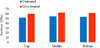 |
Fig. 6 Graph showing the change in hardness after DCT in comparison to untreated tool. |
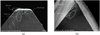 |
Fig. 7 Scanning electron microscopy images for analysis of flank wear in (a) untreated and (b) cryo-treated. |
 |
Fig. 8 Main effect plots for flank wear (a) untreated, (b) cryo-treated and for power consumption, (c) untreated, (d) treated. |
 |
Fig. 9 A graphical representation of variation in flank wear (a) and power consumption (b) for each experimental run. |
5 Conclusion and future work
Hardness and flank wear are the two vital parameters in deciding the tool life. Though the general literature says that cryo-treatment brings in morphological changes, there are no specific investigations in analyzing the impact of deep cryo-treatment on the hardness, flank wear, and power consumption of cutting tool used for dry machining. This study focuses on the advent of CT and tempering on hardness and flank wear of AISI M2 HSS cutting tool used in machining of C45 steel. We found an improvement of 14.9% in hardness, whereas growth in flank wear resistance was noted to be 125% which gradually reduced with increasing cutting speed. In this study, the Taguchi technique is used to obtain optimal machining parameters in the cutting of C45 steel under the dry conditions. The experimental results were evaluated using ANOVA.
The following main conclusion may be drawn on behalf of this study:
-
Cryo-treatment profoundly improves the wear resistance and hardness, which can be attributed to the transformation of soft retained austenite into harder martensite along with the formation of fine carbide particles in the tool.
-
At all combination of cutting conditions, deep cryo-treated tool performed exceptionally well while being consistent as compared to its untreated counterpart. A low-temperature tempering was found beneficial as it implied positive effects on hardness, flank wear resistance, and power optimization.
-
Through SEM analysis observation (and chemical analysis data of chips), we found that the flank wear region in treated tool exhibited surface supremacy, while the same region in untreated was rough and sported visible abrasive wear marks along with the formation of BUE.
Because of Taguchi trials, it was found that cutting speed is the dominating factor affecting the flank wear, while feed was the most significant factor in deciding the power consumption.
References
- S. Kumar et al., Deep cryogenic treatment of AISI M2 tool steel and optimization of its wear characteristics using Taguchi approach, Arab. J. Sci. Eng. 43 , 1–13 (2018) [CrossRef] [Google Scholar]
- E. Lassner et al., Tungsten, tungsten alloys, and tungsten compounds, in: Ullmann's Encyclopedia of Industrial Chemistry, 1996 [Google Scholar]
- E.E. Donath, M. Hoering, Early coal hydrogenation catalysis, Fuel Process. Technol. 1 , 3–20 (1977) [CrossRef] [Google Scholar]
- A.M. Brown, E.M. Klier, Machinable metal-matrix composite and liquid metal inflation process for making same, U.S. Patent No. 5,511,603, 30 April 1996. [Google Scholar]
- V. Firouzdor, E. Nejati, F. Khomamizadeh, Effect of deep cryogenic treatment on wear resistance and tool life ofM2 HSS drill, J. Mater. Process. Technol. 206 , 467–472 (2008) [CrossRef] [Google Scholar]
- J. Patscheider, S. Vepřek, Application of low-pressure hydrogen plasma to the conservation of ancient iron artifacts, Stud. Conserv. 31 , 29–37 (1986) [CrossRef] [Google Scholar]
- S. Kalia, S.-Y. Fu (Eds.), Polymers at cryo-genic temperatures (Springer, Berlin, Heidelberg, 2013) [CrossRef] [Google Scholar]
- A.A. Baker, M.L. Scott, Composite materials for aircraft structures (AIAA, Reston, VA, 2004) [Google Scholar]
- R.B. Scott, Cryogenic engineering (Van Nostrand, Princeton, NJ, 1959) [Google Scholar]
- S. Balasubramanian, M.K. Gupta, K.K. Singh, Cryogenics and its application with reference to spice grinding: a review, Crit. Rev. Food Sci. Nutr. 52 , 781–794 (2012) [CrossRef] [Google Scholar]
- C. Cai et al., Rock pore structure damage due to freeze during liquid nitrogen fracturing, Arab. J. Sci. Eng. 39 , 9249–9257 (2014) [CrossRef] [Google Scholar]
- S.Y. Hong, Y. Ding, Cooling approaches and cutting temperatures in cryogenic machining of Ti-6Al-4V, Int. J. Mach. Tool. Manuf. 41 , 1417–1437 (2001) [CrossRef] [Google Scholar]
- M. El Mehtedi et al., Analysis of the effect of deep cryogenic treatment on the hardness and microstructure of X30 CrMoN 15 1 steel, Mater. Des. 33 , 136–144 (2012) [CrossRef] [Google Scholar]
- A. Molinari et al., Effect of deep cryogenic treatment on the mechanical properties of tool steels, J. Mater. Process. Technol. 118 , 350–355 (2001) [CrossRef] [Google Scholar]
- E. Avallone, T. Baumeister, Mark's standard handbook for mechanical engineers (McGraw-Hill, New York, 2017) [Google Scholar]
- N.S. Kalsi, R. Sehgal, V.S. Sharma, Cryogenic treatment of tool materials: a review, Mater. Manuf. Process. 25 , 1077–1100 (2010) [CrossRef] [Google Scholar]
- Z.-M. Huang et al., A review on polymer nanofibers by electrospinning and their applications in nanocomposites, Compos. Sci. Technol. 63 , 2223–2253 (2003) [CrossRef] [Google Scholar]
- M. Pellizzari et al., Deep cryogenic treatment of AISI M2 high-speed steel, Int. J. Microstruct. Mater. Prop. 3 , 383–390 (2008) [Google Scholar]
- T.V. Sreerama Reddy, et al., Machinability of C45 steel with deep cryogenic treated tungsten carbide cutting tool inserts, Int. J. Refract. Metals Hard Mater. 27 , 181–185 (2009) [CrossRef] [Google Scholar]
- S. Kumar et al., The effects of cryogenic treatment on cutting tools, IOP Conf. Ser.: Mater. Sci. Eng. 225 , 012104 (2017) [CrossRef] [Google Scholar]
- N.B. Dhokey et al., Metallurgical investigation of cryogenically cracked M35 tool steel, Eng. Fail. Anal. 21 , 52–58 (2012) [CrossRef] [Google Scholar]
- I. Reddy et al., Characterization and performance evaluation of HSS cutting tools under deep cryogenic treatment, Int. J. Eng. Sci. 5 , 2319 (2015) [Google Scholar]
- J. Khedkar, A.S. Khanna, K.M. Gupt, Tribological behavior of plasma and laser coated steels, Wear 205 , 220–227 (1997) [CrossRef] [Google Scholar]
- R.B. Solé, Optimal design of sustainable chemical processes via a combined simulation-optimization approach [Google Scholar]
- S. Ebnesajjad, Handbook of adhesives and surface preparation: technology, applications and manufacturing (William Andrew, New Year, 2010) [Google Scholar]
- J. Antony, Taguchi or classical design of experiments: a perspective from a practitioner, Sensor Rev. 26 , 227–2303 (2006) [CrossRef] [Google Scholar]
- A. Aggarwal et al., Optimizing power consumption for CNC turned parts using response surface methodology and Taguchi's technique comparative analysis, J. Mater. Process. Technol. 200 , 373–384 (2008) [CrossRef] [Google Scholar]
- A. Palanisamy, T. Selvaraj, S. Sivasankaran, Optimization of turning parameters of machining incoloy 800H super alloy using cryogenically treated multilayer CVD coated tool, Arab. J. Sci. Eng. 43 , 1–14 (2018) [CrossRef] [Google Scholar]
- C.B. Reddy, V. Diwakar Reddy, C. Eswaran Reddy, Experimental investigations on MRR and surface roughness of EN 19& SS 420 Steels in wire EDM using Taguchi method, Int. J. Eng. Sci. Technol. 4 , 4603–4614 (2012) [Google Scholar]
- P. Baldissera, C. Delprete, Effects of deep cryogenic treatment on static mechanical properties of 18NiCrMo5 carburized steel, Mater. Des. 30 , 1435–1440 (2009) [CrossRef] [Google Scholar]
Cite this article as: Santosh Kumar, Mohammed Riyaz Ahmed, Lokesha M, Manjunath LH, Investigation of machinability characteristics on C45 steel with cryogenically treated M2 HSS tool using statistical technique, Int. J. Simul. Multidisci. Des. Optim. 10, A5 (2019)
All Tables
Results of quality characteristics of flank wear and power consumption for untreated and cryo-treated, respectively.
All Figures
|
Fig. 1 A symbolic representation of experimental setup depicting workpiece being machined by cutting tool. Data acquisition is done after dynamometer senses force and fed to local server/host for analysis. |
| In the text | |
|
Fig. 2 A typical representation of cryogenic treatment process. |
| In the text | |
|
Fig. 3 Deep cryogenic treatment cycle with double tempering. |
| In the text | |
|
Fig. 4 M2 HSS tool before and after profile grinding. |
| In the text | |
|
Fig. 5 Electronic dispersive spectrography of the deep cryo-treated tool. |
| In the text | |
|
Fig. 6 Graph showing the change in hardness after DCT in comparison to untreated tool. |
| In the text | |
|
Fig. 7 Scanning electron microscopy images for analysis of flank wear in (a) untreated and (b) cryo-treated. |
| In the text | |
|
Fig. 8 Main effect plots for flank wear (a) untreated, (b) cryo-treated and for power consumption, (c) untreated, (d) treated. |
| In the text | |
|
Fig. 9 A graphical representation of variation in flank wear (a) and power consumption (b) for each experimental run. |
| In the text | |
Current usage metrics show cumulative count of Article Views (full-text article views including HTML views, PDF and ePub downloads, according to the available data) and Abstracts Views on Vision4Press platform.
Data correspond to usage on the plateform after 2015. The current usage metrics is available 48-96 hours after online publication and is updated daily on week days.
Initial download of the metrics may take a while.