")
")
| Issue |
Int. J. Simul. Multisci. Des. Optim.
Volume 5, 2014
|
|
|---|---|---|
| Article Number | A12 | |
| Number of page(s) | 7 | |
| DOI | https://doi.org/10.1051/smdo/2013017 | |
| Published online | 10 February 2014 | |
Article
The periodic resin configuration design for ceramic-resin composite structure using topology optimization
Engineering Simulation and Aerospace Computing (ESAC), The Key Laboratory of Contemporary Design and Integrated Manufacturing Technology, Northwestern Polytechnical University, Xi’an, Shaanxi
710072, P.R. China
* e-mail: This email address is being protected from spambots. You need JavaScript enabled to view it.
Received:
4
June
2013
Accepted:
13
November
2013
Abstract
The ceramic-resin composite structure has broad prospects in many fields like rapid casting and thermal protection. Due to the coefficient of thermal expansion (CTE) of resin is about 10 times higher than that of ceramic, the excessive thermal expansion of the resin pattern will lead to the undesirable crack of the ceramic shell during the heating procedure. The proposed approach is to find a reasonable resin configuration minimizing the thermal stress in the ceramic shell. Simultaneously, the mechanical stiffness of the whole structure should be maintained at a certain level to resist the pressure applied on the ceramic shell. In the actual production, the periodic resin configurations are more operable than the disordered configuration, so finding reasonable periodic resin configurations for ceramic-resin composite structure has lots of significance. The purpose of this paper is to introduce the topology optimization method into the periodic resin configuration design for ceramic-resin composite structure. A structural topology optimization procedure in combination with thermo-mechanical finite element analysis has been developed. A single-layer periodic model and a double-layer periodic model are optimized and respective CAD models are rebuilt according to the optimal results. By comparing with the existing hexagonal honeycomb configuration, two optimal designs have shown better performances both in reducing the thermal stress in the ceramic shell and maintaining the stiffness of the whole structure.
Key words: Ceramic-resin composite structure / Thermal stress / Periodic resin configuration / Topology optimization
© J.H. Zhu et al., Published by EDP Sciences, 2014
 This is an Open Access article distributed under the terms of the Creative Commons Attribution License (http://creativecommons.org/licenses/by/4.0), which permits unrestricted use, distribution, and reproduction in any medium, provided the original work is properly cited.
1 Introduction
The ceramic-resin composite structure has broad prospects in many fields such as rapid casting and thermal protection. In rapid casting field, compared with the traditional investment casting processes, rapid casting based on the stereolithography (SL) prototype resin patterns provides a better precision and avoids the consumption of the metal. At the same time, the ceramic-resin composite structure can be used as the thermal protection tile in high speed aircrafts for its excellent heat resistance, corrosion resistance, good stiffness and relatively lightweight.
However, there are several problems stand in the way of the achievement of widespread use of the ceramic-resin composite structure. One of the key difficulties is to avoid the crack of the ceramic shell during the heating of the resin pattern. Under normal circumstances, as a thermoset material, the epoxy resin doesn’t melt but continues expanding until to burns out at around 1000–1200 °C with sufficient oxygen in the procedure of heating. Since the coefficient of thermal expansion (CTE) of the resin is about 10 times higher than that of the ceramic shell, during the heating process, a significant thermal expansion of the resin pattern will generate thermal stresses in the ceramic shell. If the maximum thermal stress reaches a certain value before resin pattern burns out, the unfortunate crack of the ceramic shell will take place and lead to the fail of the rapid casting immediately. So the satisfactory resin structure should collapse under the influence of its own expansion before the ceramic shell crack, at the same time, the mechanical stiffness of the whole structure should be maintained at a certain level to resist the pressure applied on the ceramic shell. To solve this problem, reasonable resin configurations should be found to meet above requirements. Among various resin configurations, the periodic resin configurations have special advantages in the convenience of manufacturing and this is one of the emphases of this paper. The ceramic-resin composite structure with single-layer periodic resin configuration is shown in Figure 1.
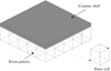 |
Figure 1. Ceramic-resin composite structure with single-layer periodic resin configuration. |
During the past decades, some prior studies have been made intensively. Hauge and Dickens studied the reasons and solutions to the shell crack problem [1, 2]. Among others, Jacobs hypothesized that the crack of the ceramic shell could be prevented when the thickness of resin pattern shell is thinner than a so-called critical section thickness [3, 4]. Hague and Dickens conducted a series of researches on the heating experiments with solid and hollowed SL patterns and observed that the shell cracking always took place at the temperatures below the glass transition temperature of epoxy resin [1, 2]. Later, 3D systems developed QuickCast platform and proposed several lattice styles [5]. Norouzi and Rehmati introduced a new octagonal internal lattice structure, which leads a great reduction in maximum stresses exerted on the ceramic shell [6]. Gu et al. [7] introduced the topology optimization method into the lattice structure configuration design for rapid casting patterns for the first time and proposed several 2D and 3D configurations. When used as thermal protection tile, the hexagonal honeycomb resin configuration as shown in Figure 2 is widely used for ceramic-resin composite structure in practical production.
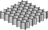 |
Figure 2. Hexagonal honeycomb resin configuration. |
In this paper, we propose a structure topology optimization procedure in combination with thermo-mechanical finite element analysis to find better periodic resin configurations for the ceramic-resin composite structure. Numerical modeling about the mathematical formulation of the objective function and design constraints is established and optimal periodic resin configurations for single-layer model and double-layer model are sought out. By comparing with the existing hexagonal honeycomb resin configuration, two optimal designs have shown better performances both in reducing the stress in the ceramic shell and maintaining the stiffness of the whole structure.
2 Numerical modeling
Optimal designs intend to avoid the crack of the ceramic shell by decreasing the maximum thermal stress inside. Besides, the whole structure must maintain the mechanical stiffness at a high enough level to support the external mechanical loads. Thus the resin configuration design comes down to a topology optimization under the thermal-mechanical loads condition. Here, we can summarize the following goals that the topology optimization should attain:
-
Maintain the mechanical stiffness of the whole structure at a certain level.
-
Minimize the thermal stress in the ceramic shell.
-
Save the consumption of the resin material.
To carry out the topology optimization, two load cases, i.e. the thermal load and the pressure load are applied. In the mechanical model as shown in Figure 3a, a uniform pressure load of 1 Mpa is used to simulate the external load applied on the upper surface of the ceramic shell. In the thermal model as shown in Figure 3b, an isothermal temperature of 60 °C is applied on both the resin pattern and the ceramic shell to generate the critical thermal expansion. The two models share the same boundary conditions, suppose the composite structure is taken out from a large area, four bottom sides are fixed and four side faces are restrained to move within the corresponding faces, as shown in Figure 3.
 |
Figure 3. Two load cases of model. |
Therefore, the mathematical formulation of the topology optimization problem can be expressed as: (1)where x is the vector of design variables, i.e. the pseudo-densities which vary between 0 and 1 to describe the material distribution over the design domain. σC is the Von-Mises stress in the ceramic shell due to the temperature effect. V is volume of the design domain. C is the strain energy of the whole structure related to the mechanical model and it is inversely proportional to the structure stiffness. C(U) and V(U) are the upper bounds of the strain energy and the material volume over the design domain, respectively. x(L) is the lower bound of the pseudo-densities to avoid the singularity of the element stiffness matrix when the element material is removed.
Since the material properties of the cured resin will change with the variation of temperature during the heating procedure, the material parameters and experiment conditions must be defined first. The results of preliminary experiment show that the thermal stress in the ceramic shell is maximized when temperature is about 60 °C. That’s why we use the temperature at 60 °C as the thermal environment in thermal model for topology design optimization. Thus we use the temperature at 60 °C as the severe case to ascertain the material properties. The material properties are shown in Table 1, and the reference temperature is set to be 20 °C.
Material properties used in the topology optimization.
3 Numerical study
As shown in Figure 4, two simple models, i.e. the single-layer model and the double-layer model are optimized, respective CAD models are rebuilt according to the optimal results and then compared with the existing hexagonal honeycomb resin configuration.
 |
Figure 4. Two simple models used to evaluate the stress level in the ceramic shell. |
A single-layer model
As shown in Figure 4a, the size of the periodic resin part is 200 mm × 200 mm × 40 mm, a 2 mm thick resin layer and a 10 mm thick ceramic shell cover on the upper surface successively. The periodic part is subdivided into 25 basic cells which share the same material distribution and every basic cell is a cube with 40 mm in side length.
By allowing the periodic part’s volume fraction of 40% and constraining the strain energy of the whole structure to 40 J, adopt the material whose pseudo-density higher than 0.7, the optimal design of the resin configuration and a single basic cell are shown in Figure 5. Then a CAD model shown in Figure 6 is rebuilt accordingly.
 |
Figure 5. The optimal result obtained with topology optimization. |
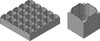 |
Figure 6. The rebuilt CAD model of periodic resin configuration. |
To compare the optimal design with the existing hexagonal honeycomb resin configuration, the optimal model and the hexagonal honeycomb model shown in Figure 7 are analyzed respectively by finite element simulation. Two models share the same boundary conditions and load cases, and the optimal model uses less resin material than the hexagonal honeycomb model. The thermal stress distribution in the ceramic shell under the temperature load and the deformation of the ceramic shell under pressure load are shown in Figures 8 and 9 respectively. The overall comparison of two models is shown in Table 2.
 |
Figure 7. The optimal model and the hexagonal honeycomb model to be analyzed. |
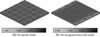 |
Figure 8. The thermal stress distribution in the ceramic shell under temperature load (Mpa). |
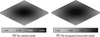 |
Figure 9. The deformation of the ceramic shell under pressure load (mm). |
Comparison of the optimal model and the hexagonal honeycomb model.
As we can learn from Table 2, compared with the hexagonal honeycomb model, the optimal model reduce the maximum thermal stress in the ceramic shell from 2.643 Mpa to 1.709 Mpa, meanwhile, the strain energy of the whole structure decreases from 128.324 J to 62.716 J, and all these are in the precondition of less consumption of resin materials.
A double-layer model
As shown in Figure 4b, the size of the periodic resin part is 200 mm × 200 mm × 80 mm, the thicknesses of the resin layer and the ceramic shell are still 2 mm and 10 mm, respectively. The periodic part is subdivided into 5 × 5 × 2 basic cells with 40 mm in side length. By allowing the periodic part’s volume fraction of 40% and constraining the strain energy of the whole structure to 55 J, adopt the material whose pseudo-density higher than 0.75, the optimal design of the periodic resin part and a single basic cell are shown in Figure 10, then the rebuilt optimal CAD model shown in Figure 11 is established. Be similar with the single-layer case, the double-layer optimal model and the hexagonal honeycomb model shown in Figure 12 are analyzed respectively. The boundary conditions and load cases remain the same. The thermal stress distribution in the ceramic shell under temperature load is shown in Figure 13, the deformation of the ceramic shell under pressure load is shown in Figure 14, and the overall comparison of two models is shown in Table 3.
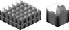 |
Figure 10. The optimal result obtained with topology optimization. |
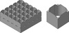 |
Figure 11. The rebuilt CAD model of periodic resin configuration. |
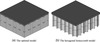 |
Figure 12. The optimal model and the hexagonal honeycomb model to be analyzed. |
 |
Figure 13. The thermal stress distribution in the ceramic shell under temperature load (Mpa). |
 |
Figure 14. The deformation of the ceramic shell under pressure load (mm). |
Comparison of the optimal model and the hexagonal honeycomb model.
As shown in Table 3, the optimal model uses less resin materials than the hexagonal honeycomb model, whereas the maximum thermal stress in the ceramic shell under temperature load decreases from 2.845 Mpa to 1.709 Mpa. In the meantime, the strain energy of the whole structure under pressure load decreases from 14.84 J to 10.58 J.
4 Conclusion
In this paper, techniques of topology optimization are introduced to find better periodic resin configurations for the ceramic-resin composite structure. The optimization approach is carried out to solve the crack problem of the ceramic shell by reducing the maximum thermal stress in the shell. At the same time, the mechanical stiffness of the whole structure and the consumption of the resin material are taken into consideration. In the tested examples, reasonable optimal designs are obtained by topology optimization. Compared with the existing hexagonal honeycomb configuration, the optimal designs not only use less resin materials, but also are both stiffer and better in reducing the maximum thermal stress in the ceramic shell.
References
- Hague R, Dickens PM. 1995. Stresses created in ceramic shells using QuickCast models, in Proceedings of the Solid Freeform Fabrication Symposium, Marcus H, Editors. University of Texas at Austin. p. 242–252. [Google Scholar]
- Hague R, Dickens PM. 1996. Finite element analysis and strain gauging of the stereolithography/investment casting system, in Proceedings of the Solid Freeform Fabrication Symposium, Bourell D, Editors. University of Texas at Austin. p. 523–538. [Google Scholar]
- Jacobs PF. 1996. Stereolithography and other RP&M technologies: from rapid prototyping to rapid tooling. ASME Press: New York, NY. [Google Scholar]
- Jacobs PF. 1995. Rapid tooling. World Class Design to Manufacture, 2(6), 42–50. [CrossRef] [Google Scholar]
- Hague R. 2001. Structural design and resin drainage characteristics of QuickCast 2.0. Rapid Prototyping Journal, 7(2), 66–72. [CrossRef] [Google Scholar]
- Norouzi Y, Rehmati S. 2009. A novel lattice structure for SL investment casting patterns. Rapid Prototyping Journal, 4(14), 255–263. [CrossRef] [Google Scholar]
- Gu XJ, Zhu JH, Zhang WH. 2012. The lattice structure configuration design for stereolithography investment casting pattern using topology optimization. Rapid Prototyping Journal, 18(5), 353–361. [CrossRef] [Google Scholar]
Cite this article as: Zhu JH, Li Q & Zhang WH: The periodic resin configuration design for ceramic-resin composite structure using topology optimization. Int. J. Simul. Multisci. Des. Optim., 2014, 5, A12.
All Tables
All Figures
|
Figure 1. Ceramic-resin composite structure with single-layer periodic resin configuration. |
| In the text | |
|
Figure 2. Hexagonal honeycomb resin configuration. |
| In the text | |
|
Figure 3. Two load cases of model. |
| In the text | |
|
Figure 4. Two simple models used to evaluate the stress level in the ceramic shell. |
| In the text | |
|
Figure 5. The optimal result obtained with topology optimization. |
| In the text | |
|
Figure 6. The rebuilt CAD model of periodic resin configuration. |
| In the text | |
|
Figure 7. The optimal model and the hexagonal honeycomb model to be analyzed. |
| In the text | |
|
Figure 8. The thermal stress distribution in the ceramic shell under temperature load (Mpa). |
| In the text | |
|
Figure 9. The deformation of the ceramic shell under pressure load (mm). |
| In the text | |
|
Figure 10. The optimal result obtained with topology optimization. |
| In the text | |
|
Figure 11. The rebuilt CAD model of periodic resin configuration. |
| In the text | |
|
Figure 12. The optimal model and the hexagonal honeycomb model to be analyzed. |
| In the text | |
|
Figure 13. The thermal stress distribution in the ceramic shell under temperature load (Mpa). |
| In the text | |
|
Figure 14. The deformation of the ceramic shell under pressure load (mm). |
| In the text | |
Current usage metrics show cumulative count of Article Views (full-text article views including HTML views, PDF and ePub downloads, according to the available data) and Abstracts Views on Vision4Press platform.
Data correspond to usage on the plateform after 2015. The current usage metrics is available 48-96 hours after online publication and is updated daily on week days.
Initial download of the metrics may take a while.